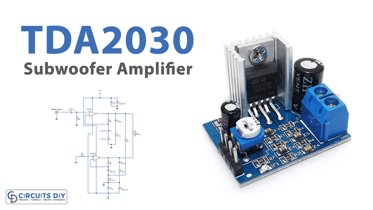
In this tutorial, we are going to make a “TDA2030 Subwoofer Amplifier circuit”. A subwoofer (or sub) is a loudspeaker designed to reproduce low-pitched(bass and sub-bass) audio frequencies, these frequencies are lower than those which can be generated by a woofer. The typical frequency range for a subwoofer is about 20–200 Hz for consumer products and below 100 Hz for professional live sound. They are never used alone, as intended to augment the low-frequency range of loudspeakers that cover the higher frequency bands. While the term “subwoofer” technically only refers to the speaker driver, in common parlance, the term often refers to a subwoofer driver mounted in a speaker enclosure, often with a built-in amplifier.
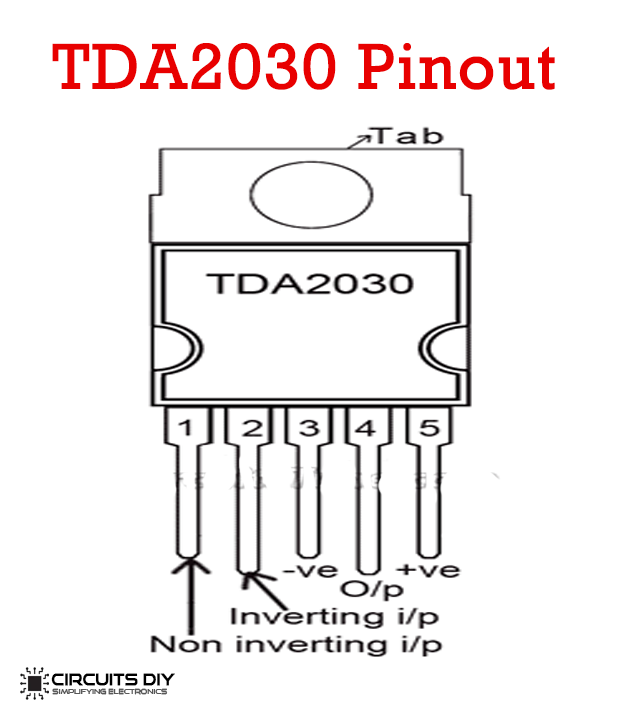
Here we design a simple subwoofer amplifier circuit by using TDA2030 IC, and this is intended for use as a low-frequency class-AB amplifier. It provides 14 watts of output, by adding another stage it may give an output of up to 30 watts. This circuit needs a split power supply with a one-amp current rating for better performance. And use a heat sink over TDA2030 IC to avoid thermal runaway. This IC comes in a Pentawatt Horizontal package and has a wide range of operating voltages up to 36V. And it is capable of working in a single or split power supply.
Hardware Required
| S.no | Component | Value | Qty |
|---|---|---|---|
| 1. | IC | TDA2030 | 1 |
| 2. | Resistor | 22KΩ,680Ω,1Ω | 4,2,2 |
| 3. | Capacitor | 0.1uf,0.22uf,2.2uf/16V,22uf/25V,100uf/25V | 2,2,1,2,2 |
| 4. | Connecting Wires | – | |
| 5. | Speaker | 1 | |
| 6. | Battery | 15V | 1 |
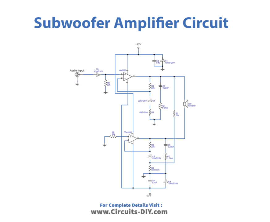
Circuit Diagram
Details of the main part of this circuit are as follows.
Working Explanation
As we can see in the circuit, there are two TDA2030 amplifiers. The here upper side amplifier output is connected to the speaker +ve terminal and the lower side amplifier O/P is connected to the -ve terminal of the speaker. Audio input is applied to the non-inverting input of IC1 and IC2 and grounded through the R8 resistor. Each amplifier takes feedback through inverting input. This circuit uses a split power supply (+15V, GND, -15V), by using this bridge amplifier configuration we can get output power up to 30 watts.
Applications
Used in Hi-Fi field applications such as home stereo, self-powered loudspeakers, and top-class TV.