Power failure is common everywhere, therefore an emergency light always comes in handy. Today we are going to demonstrate a power failure light circuit. This circuit is using 10 bright white LEDs because they produce more light and consume less power. These LEDs will activate automatically in the absence of mains power, more LEDs can be added to this circuit to produce more light considering that total current consumption should not exceed the supply current. This project is one of the simplest, most cost-effective, and most useful DIY projects. Since it is used during the power failure it should last long that’s why we chose this combination of the components.
Hardware Components
The following components are required to make Power Failure Light Circuit
| S.no | Components | Value | Qty |
|---|---|---|---|
| 1. | Step down Transformer | 230V-12V/500 mA | 1 |
| 2. | Diode | 1N4001 | 1 |
| 3. | Capacitor | 1000uF/50V | 1 |
| 4. | Resistor | 390 ohms, 1K | 10, 1 |
| 5. | LED | – | 11 |
| 7. | Relay | 12V | 1 |
| 8. | Switch | – | 1 |
| 9. | Battery | 4.5V or 1.5×3 | 3 |
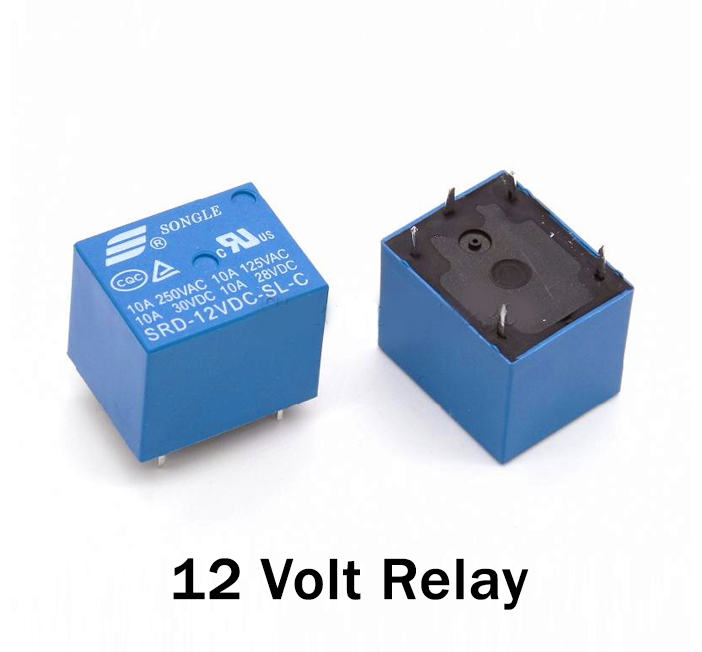
Relay Pinout
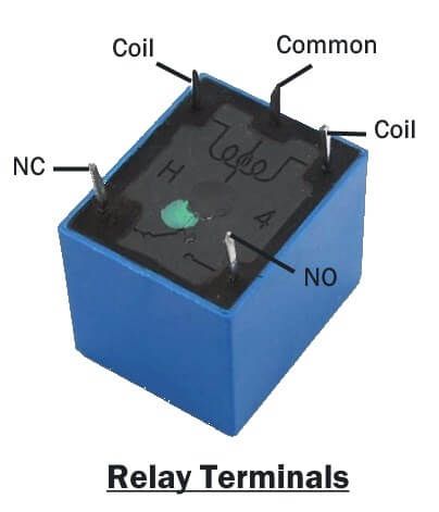
For a detailed description of pinout, dimension features, and specifications download the datasheet of Relay
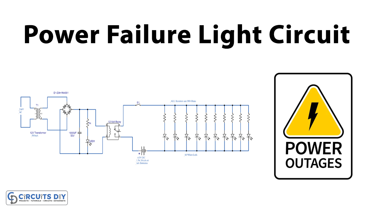
Power Failure Light Circuit
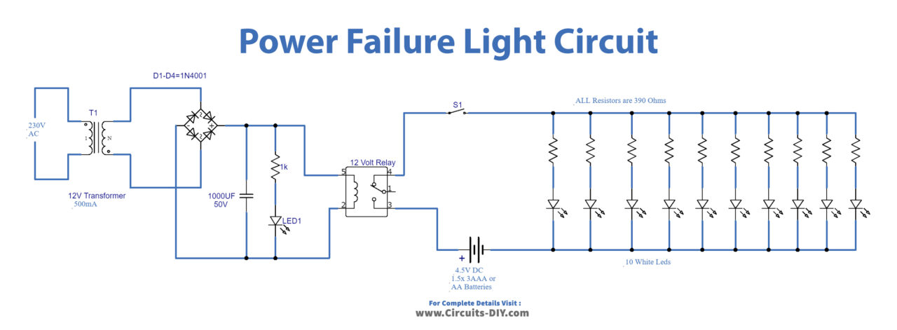
Working Explanation
This circuit is divided into two parts. The first part is a circuit of a 12V power supply and the second part is an LED lights lamp. In the first part, we are converting 230V AC into low voltage DC. We are using a transformer to step down the 230 voltage to 12V, it is rectified through a diode bridge. A 1000uF capacitor is used for noise filtration.
The second part of this circuit is where the main function is being performed, which is to automatically activate the LED lights on power failure. We are using a 12V relay to automate this. A 4.5 V battery is connected to the arrays of LEDs through a relay. When the power is coming from the 12V supply to the relay it will energize and goes towards the NO (normally open) terminal, it will disconnect the 4.5V battery from the LED lamp circuit. In the absence of mains power the relay will turn off and the lever will connect to the NC (normally closed) circuit which will activate the battery connected to the LAMP circuit and it will turn ON. This process will repeat depending on the availability of the main power.