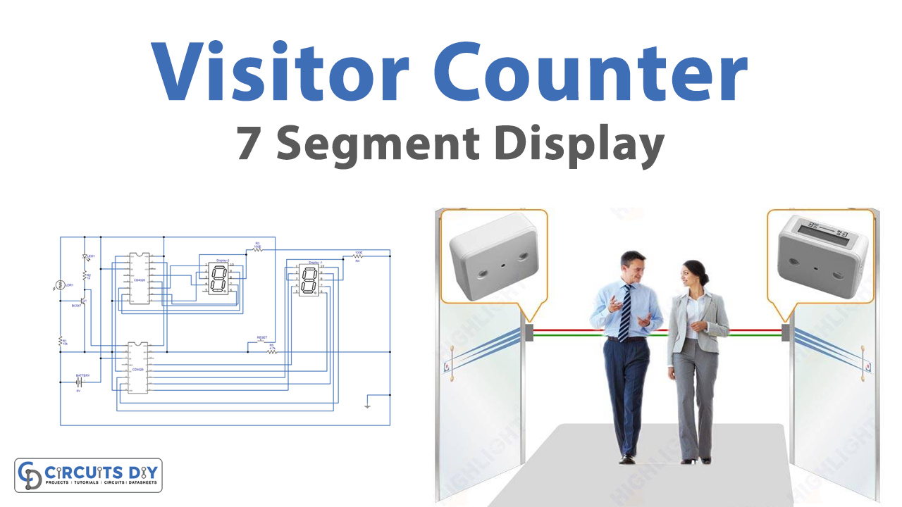
Introduction
Counting visitors is a useful technique for any company or organization. The quantity of individuals that walk into a company, firm, store, or shop usually suggests that you are doing much to attract interest. When you compare the total number of visits to the total number of sales, you get your conversion rate, which is a priceless piece of data that provides you with an idea of how well your business is doing. And, for this, you need a visitor counter device. A visitor counter is an electronic device that counts how many visitors pass through a particular path or entry. So, In this tutorial, we are going to make a “Seven segment visitors Counter”.
In the making of the circuit, we are using seven segment devices. It is a component having seven LEDs grouped in a rectangular pattern. Every LED has referred to a segment, and each of the terminals corresponds to one of the segments. We may use the binary-digit inputs to control the LEDs in segments A through G, allowing you to show decimal numbers from 0 to 9 or letters from A to F.
Hardware Required
| S.no | Component | Value | Qty |
|---|---|---|---|
| 1. | Decade Counter IC | CD4026 | 2 |
| 2. | Seven Segments Common Cathode LED | – | 2 |
| 3. | LDR | – | 1 |
| 4. | NPN Transistor | BC547 | 1 |
| 5. | LED | – | 1 |
| 6. | Push-Button Switch | – | 1 |
| 7. | Resistors | 1KΩ, 10KΩ, 4.7KΩ, 100Ω | 1, 1, 1, 2 |
| 8. | Battery | 6v | 1 |
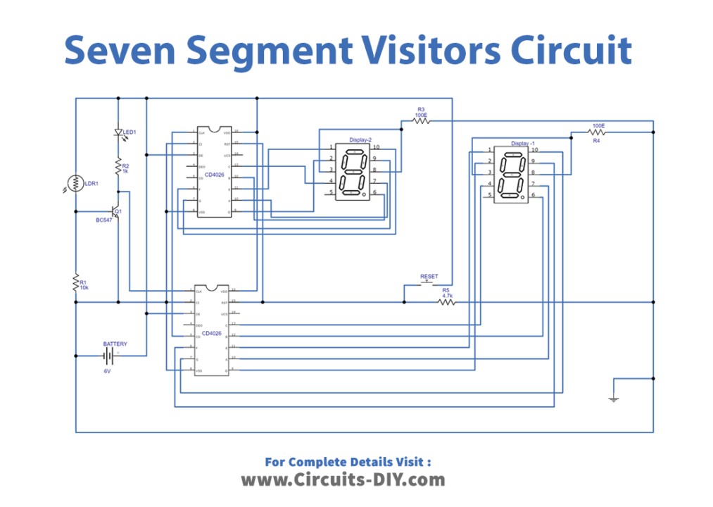
Circuit Diagram
Working Explanation
The Seven segment visitors Counter is made up of two CD4026 counter ICs, an LDR, a transistor BC547, and two seven-segment displays. LDR is utilized, which detects the shadow of a human passing its path. The seven-segment LEDs used here in this circuit are common cathode types and include a reset option, so we may reset the count at any moment.
As a person passes through the gate and his shadow falls on LDR1, the quantity of light falling on it decreases. As a result, LDR’s resistance increases, providing a clock pulse to IC1’s pin 1 through the transistor. LED1 dims for a brief while during this time, signaling that someone is approaching or departing the door.
When a clock is received at pin 1, the number on display Display 1 is incremented by one. With each individual that passes through the gate, the count on the display increases by one. One cycle ends when the count hits 9.
To cascade, another counter, IC1’s carry-out pin 5 is linked to IC2’s clock pin 1. It goes high on the following clock after count 9, providing a clock pulse to IC2, which advances its counter by one. IC1 is now restarted from the beginning.
Display 1 displays the unit’s digit, whereas DIS2 displays the count’s tenth digit. The tenth digit increases by one once each cycle is completed. Pin 15 of both ICs is linked to the ground. To reset the display to ’00,’ a reset button is there in the circuit.
Application and Uses
- It can help businesses to count their visitors to find their conversion rate.
- One can use this in seminars, conferences, etc