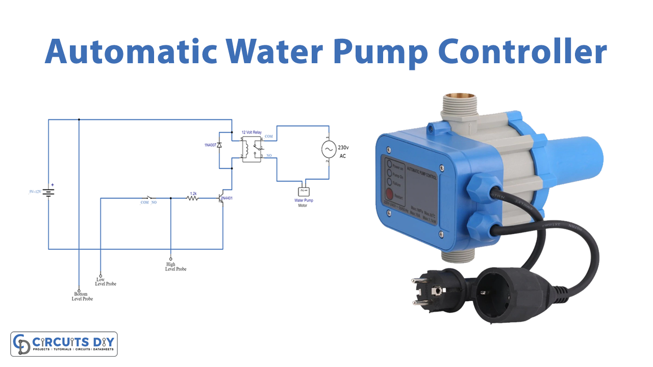
In this DIY, we are developing a “Simplest Automatic Water Pump Controller”. This circuit is the most straightforward circuit of an “automatic water pump controller”. The “Automatic Water Pump Controller system” screens the water levels and controls the pump as it is important to prevent leakages and overfilling and maximize the water storage without stuffing the tank and wasting water.
The circuit will consequently turn ON a water pump when the water level is beneath the “lower-level probe” and switch OFF automatically when the water level reaches the “full level probe.”
Hardware Components
The components required to develop an automatic water pump controller are listed below:
| S.no | Component | Value | Qty |
|---|---|---|---|
| 1. | Diode | 1N4007 | 1 |
| 2. | DPTP Relay | 24V | 1 |
| 3. | Water Pump Motor | 220V | 1 |
| 4. | Transistor | 2N4401 | 1 |
| 5. | AC Supply | 230V | 1 |
| 6. | DC Supply | 5V-12V | 1 |
| 7. | Resistor | 1.2K | 1 |
| 8. | Level Probes | – | 3 |
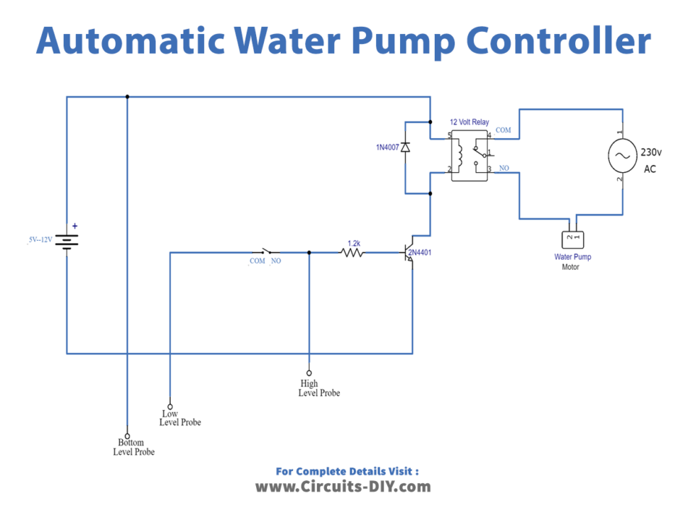
Circuit Diagram
Circuit Operation
In this section, we talk about the circuit operation of an “automatic water pump controller”. The circuit is utilizing just three segments which are a 2N4401 transistor, one 1.2K resistor, and one DPDT relay. There are three probes in the circuit which ought to be set in the water, and any thin wire will carry out the job. The “base probe” ought to be put in the base of the water, the “lower-level probe” will be set at the point from where you need to begin the water pump to fill the water, and the “full-level probe” will be set where you need to stop the water pump.
The working voltage of the circuit is 5V to 12V DC. You can utilize a battery or any attachment pack from 5V to 12V will work here. The relay voltage value ought to be used according to the working voltage.
Applications and Uses
Water pump Controller has various applications but mostly it is used in swimming pools and water tanks etc.