Introduction
LED lights are widely utilized in electronic circuitry, mostly for indication purposes. But, many circuits are totally based on LEDs. For example, Flasher circuits, flashing light units, etc. Hence, In this tutorial, we are going to make a “USB Rechargeable LED Circuit”. So the question is where can we need or use this circuit? For instance, you are in a dark place having no electricity around. Since the circuit is portable and. rechargeable, that’s why can be adopted while traveling.
Hardware Required
| S.no | Component | Value | Qty |
|---|---|---|---|
| 1. | MCP73831-2-OT | – | 1 |
| 2. | LT1932 | – | 1 |
| 3. | Schottky Diode | ZHCS400TA | 1 |
| 4. | LED, LED-G | 3,1 | |
| 5. | Inductor | 6.8µH | 1 |
| 6. | Diode | 1N4007 | 1 |
| 7. | SMD Capacitor | 4.7µF, 2.2µF | 3,1 |
| 8. | SMD Resistor | 5.1KΩ, 2KΩ, 470Ω, 1.5KΩ | 2,1,1,1 |
| 9. | liPo Battery | 3.7v 500mah | 1 |
| 10. | Button | JS102011SAQN | 1 |
| 11. | Male Connector | 105450-0101 | 2 |
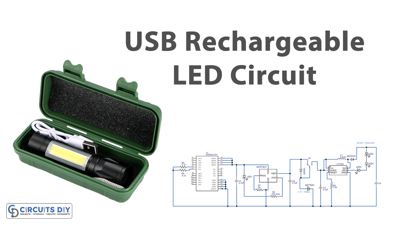
Circuit Diagram

Working Explanation
USB Rechargeable LED Circuit includes three main portions, the regulator part, then the charger section, and then the led driver circuit. The USB C connector provides a power supply to the regulator section. U1 IC is there to regulate the power supply and generated the output of 4V with 500mA of current. The IC has the PROG pin which can be used for the programming, it requires. The S1 switch connects this battery section to the LED driver circuit. Hence power supply starts to flow in that circuit which drives the LEDs that are wired in the circuit. The Schottky diode which is wired at the output side helps to prevent the circuit from reverse polarity.
Application and Uses
- With some modifications, it can be used as an LED lamp.
- It can also be utilized in LED torches.
- Also, in the flashing light circuits, etc.