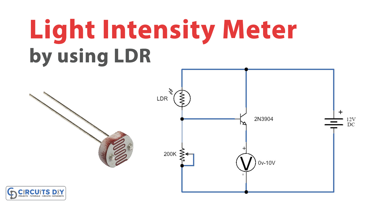
This basic light intensity meter circuit can be used in a wide range of electronic projects and experiments to calculate light intensities. The circuit is very simple and convenient using only a few LDR, variable resistor, transistor, and meter components.
The circuit utilizes an analog meter of 0 to 10 volts. You can also use any digital voltmeter by selecting the 10 or 20-volt DC measurement feature. You can also calculate the subtle changes in light intensity by using a digital millimeter. With the 200 K variable resistor, the circuit’s sensitivity can be changed.
Hardware Components
The following components are required to make Light Intensity Meter Circuit
| S.no | Components | Value | Qty |
|---|---|---|---|
| 1. | LDR | – | 1 |
| 2. | Potentiometer | 200k | 1 |
| 3. | Transistor | 2N3904 | 1 |
| 4. | DC Supply | 12V | 1 |
| 5. | Multimeter | – | 1 |
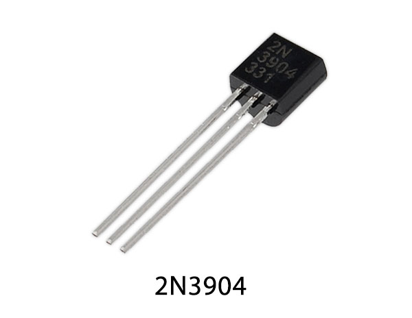
2N3904 Pinout
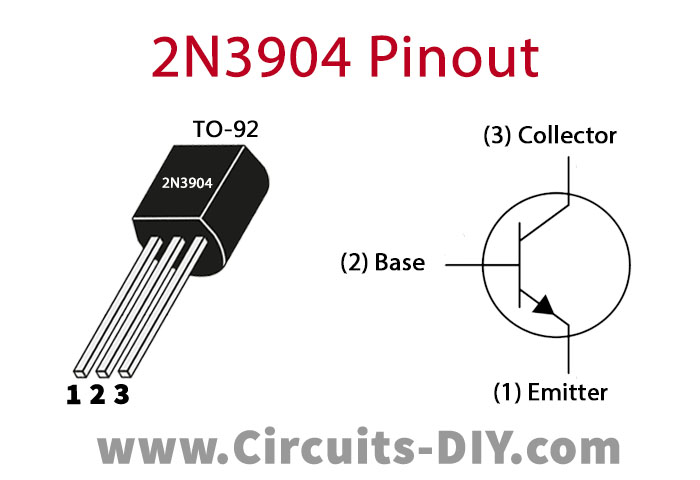
For a detailed description of pinout, dimension features, and specifications download the datasheet of 2N3904
Light Intensity Meter Circuit

Working Explanation
The light meters use a sensor called a photodiode to measure the light intensity. A photodiode is a semiconductor that transforms electrical current into incoming light. The sensor conducts a directly proportional electric current to the amount of light it detects. The filters and the lenses are installed into the photodiode As the LDR or Light-based resistor absorbs light on its surface, its resistance will begin to decrease, as a result of which the transistor will turn ON, and the
Application Uses
- A light intensity Meter is used to calculate the light intensity