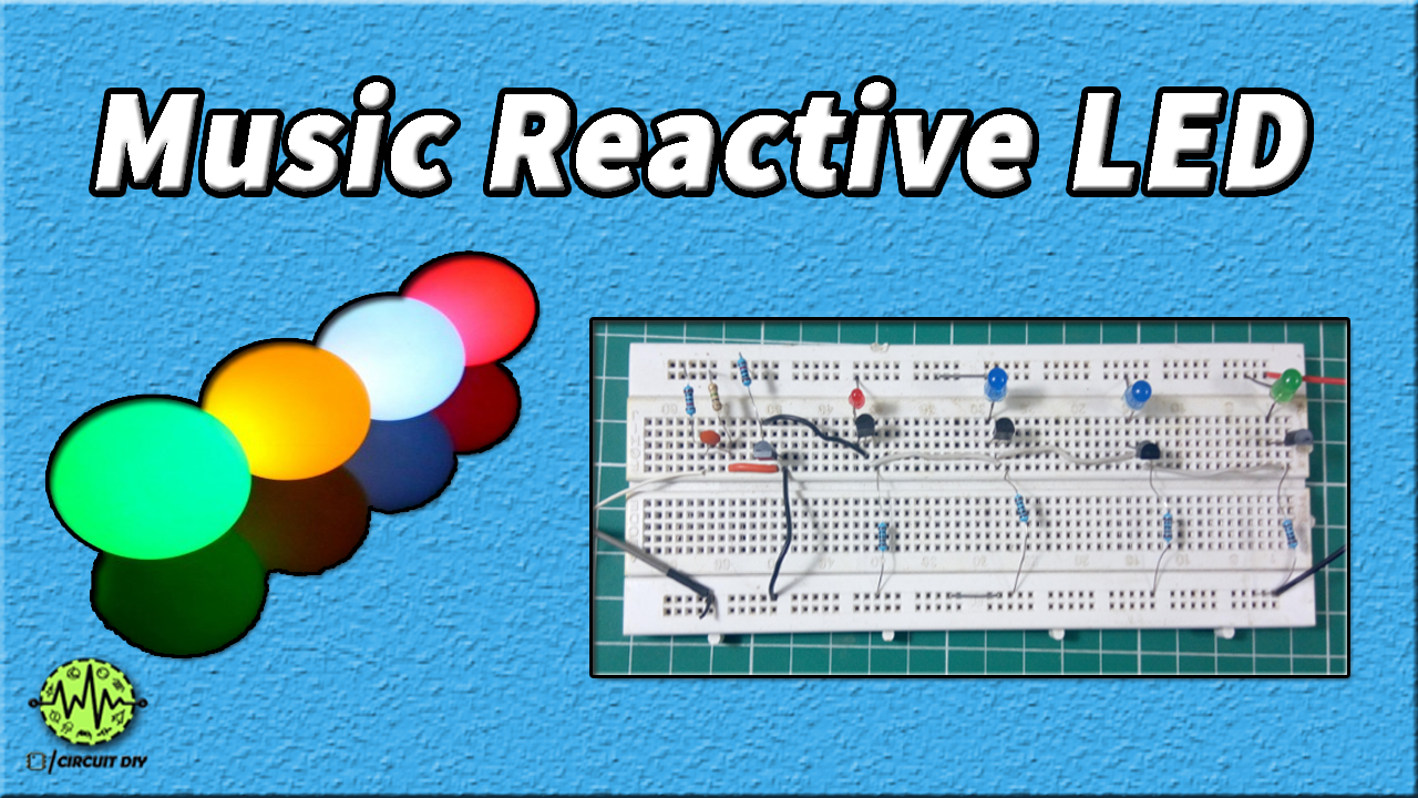
You ought to have viewed the Disco Lights or DJ lights, which Turn ON and OFF according to the beats of the music. These lights glow according to the size and pitch (volume) of music beats, essentially these are designed to select high-intensity sounds like Bass sound. So today we are going to make Music Reactive Dancing LED Circuit using transistors and a condenser mic. Watch the video for a better understanding.
Hardware Components
The following components are required to make Music Reactive LED Circuit
| S. No | Components | Value | Qty |
|---|---|---|---|
| 1. | Breadboard | – | 1 |
| 2. | Connecting Wires | – | 1 |
| 3. | Battery | 9v | 1 |
| 4. | NPN Transistor | BC547 | 5 |
| 5. | Ceramic Capacitor | 100nF | 1 |
| 6. | Resistors | 1K,10K,1M | 4,2,1 |
| 7. | Condenser Mic | – | 1 |
Useful Steps
Follow all steps carefully from the video tutorial at the end of this post (Highly Recommended).
- STEP # 1 ( Connect Transistors )
- Connect 5 BC457transistors anywhere on the breadboard
- STEP # 2 ( Connect wires )
- Connect a
wire to the base pin of one transistor to the base pin of another Do this for all four transistors. - STEP # 3 ( Connect LED )
- Connect the
+ve pin of each LED on the +ve rail and the negative pin on the collector pin of each connected transistor. - STEP # 4 ( Connect resistors )
- Connect
1K resistor to the emitter pin of each transistor to GND - STEP # 5 ( Connect transistor )
- Connect the BC547 transistor to the board
- Connect wire BTW the collector pin to the base pin of
previous ly connected transistors - Connect wire BTW emitter pin and GND
- STEP # 6 ( Connect resistor )
- Connect 10k resistor BTW to the +ve rail and the collector pin of the
newly connected transistor - STEP # 7 ( Connect resistor and capacitor )
- Connect 1M ohm resistor BTW the base pin and +ve rail
- Connect a 10k ohm resistor with 100nf capacitor to the base pin of the
transistor - STEP # 8 ( Connect mic )
- Connect mic BTW base pin and GND
- STEP # 9 ( testing )
- Connect the battery and test
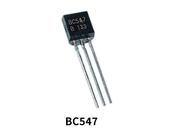
BC547 Pinout

For a detailed description of pinout, dimension features, and specifications download the datasheet of BC547 Transistor
Music Reactive LED Circuit

Working Explanation
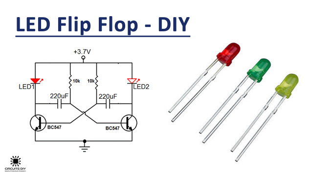
Working is really simple all the transistors here are used in cascade configuration the output of the first becomes the input of the second so the first transistor is biased such that when it detects the sound usually resistance it gives output with the same resistance so the first LED attached to it glows and similarly others
Applications
- Disco Light, DJ Light, and many other decorating ideas