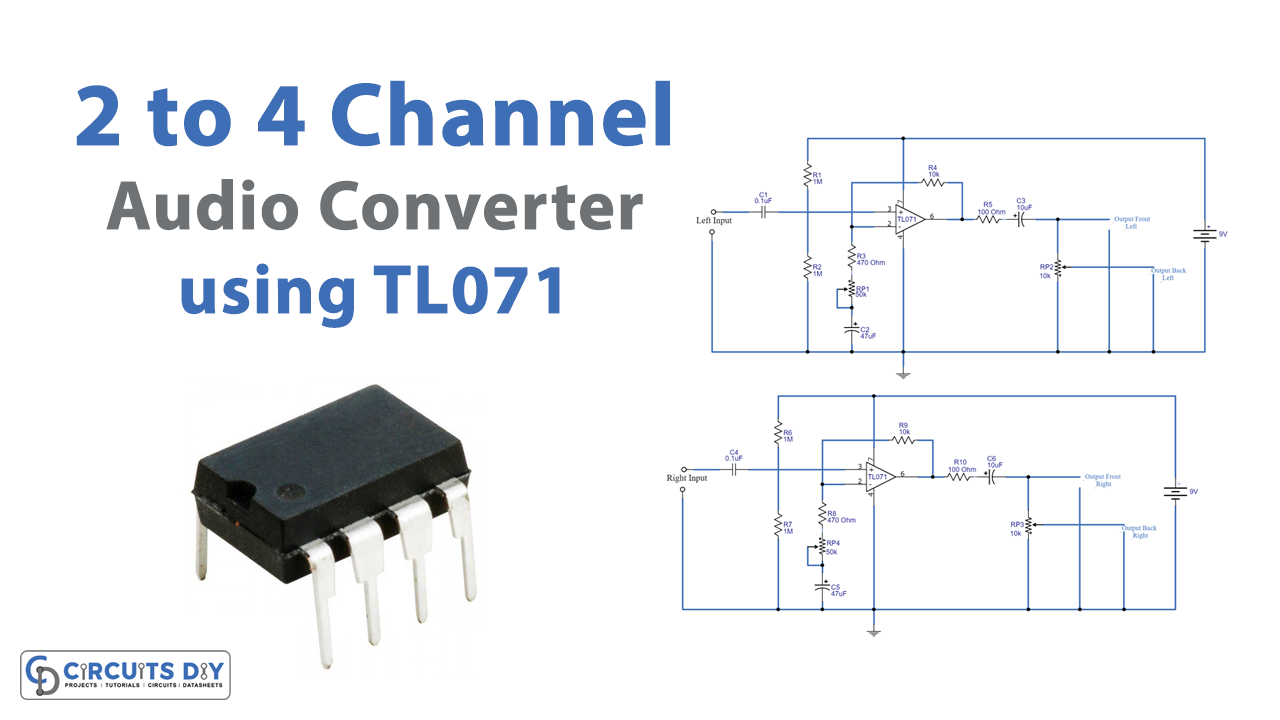
In this Tutorial, we are going to make a “2 to 4-channel audio converter using TL071”. As the name implies, an audio converter converts or transforms the audio. Thus 2 to 4 audio converter takes audio from two channels and converts that into four channels at the output. The following circuit uses TL017 IC for that purpose. Following are its features and specifications.
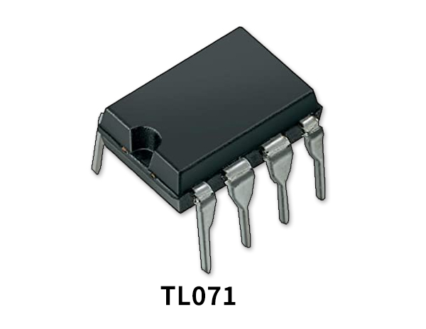
Inside TL071 is a single working amplifier. The chip comes in 8-pin packaging. The IC’s internal circuitry includes fourteen transistors, 2two JFETs, eleven resistors, one diode, one capacitor, and one epi-FET. The IC’s internal circuitry is designed to achieve minimal harmonic distortion and noise, making it excellent to be used in audio preamplification.
TL071 IC Features and Technical Specifications
- Low noise and low distortion circuitry
- Short circuit protection at the output
- Low current consumption
- Free from latch-up
- JFET used at the input
- 10mA output current
- Fast slew rate
- Very low harmonic distortion
- Wide operating voltage from 6V to 36V
- Quiescent current is only 1.4mA to 2.5mA
- Low-cost and reliable
Hardware Required
| S.no | Component | Value | Qty |
|---|---|---|---|
| 1. | IC | TL071 | 2 |
| 2. | Resistor | 10K, 1M, 10K, 100 Ohm | 2, 4, 2, 2 |
| 3. | Capacitor | 0,1uf, 10uf, 47uf | 2, 2, 2 |
| 4. | Variable Resistor | 10K, 50K | 2,2 |
Circuit Diagram
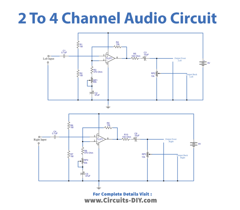
Working Explanation
The 2 to 4 Channel Audio Converter using TL071 utilizing TL071 op-amp IC as IC1 and IC2 The growth rate are computed from Resistors by using a formula: R4/R3 +1. Potentiometers VR1 and VR2 represent the modified rate of growth of each channel output signal which exits from pin 6 through R5, C3, and R10, C6. Potentiometer VR3 / 1 and VR3 / 2 knobs are used to modify the volume of each channel
Application Uses
- Car audio stereo system