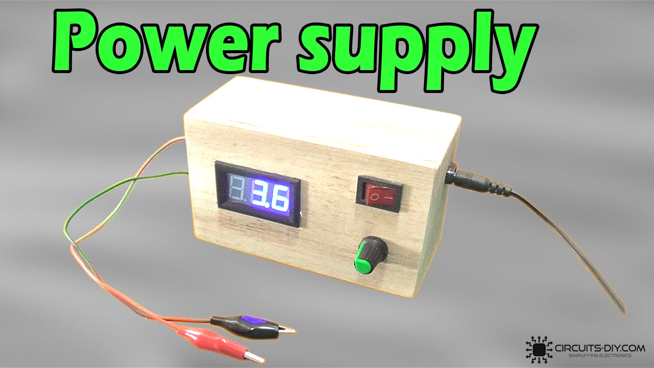
A simple adjustable power supply is an electronic device capable of converting a source(either AC/DC) from one voltage level to another. They fulfill a wide array of requirements in industrial as well as academic settings such as test bench supplies and load matching applications for variable DC drives. By Definition, an AC/DC power supply takes in an AC/DC Signal (depending upon the configuration) & shifts it to the desired voltage level. So, in today’s tutorial, we are going to design a simple Adjustable Power Supply Using LM317 Voltage Regulator IC.
The heart of this power supply is an LM317 voltage regulator IC. LM317T is a three-terminal voltage regulator IC, with a high output current value of 1.5A. The LM317 IC has many features such as current limiting, thermal protection, and safe operating area protection. It can also provide a float function for high voltage uses. If we disconnect the adjustable terminal still, LM317T will be helpful in overload protection.
JLCPCB is the foremost PCB prototype & manufacturing company in china, providing us with the best service we have ever experienced regarding (Quality, Price Service & Time).
Hardware Required
You will need the following parts to build this project:
| S.no | Component | Value | Qty |
|---|---|---|---|
| 1. | Voltage Regulator IC | LM317T | 1 |
| 2. | AC Adapter | 220V AC/12V DC | 1 |
| 3. | Digital LED Voltmeter | – | 1 |
| 4. | Resistor | 1K | 1 |
| 5. | ON/OFF switch | – | 1 |
| 6. | Heatsink | – | 1 |
| 7. | DC Power Jack | Female/3.5mm | 1 |
| 8. | Potentiometer | 10KOhm | 1 |
| 9. | Soldering Iron | 45W – 65W | 1 |
| 10. | Soldering Wire with Flux | – | 1 |
| 11. | Jumper Wires | – | As per need |
| 12. | AC Wall Outlet | 220V | 1 |
| 13. | Alligator Clips | – | 2 |
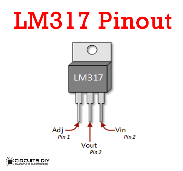
LM317 Pinout
Useful Steps
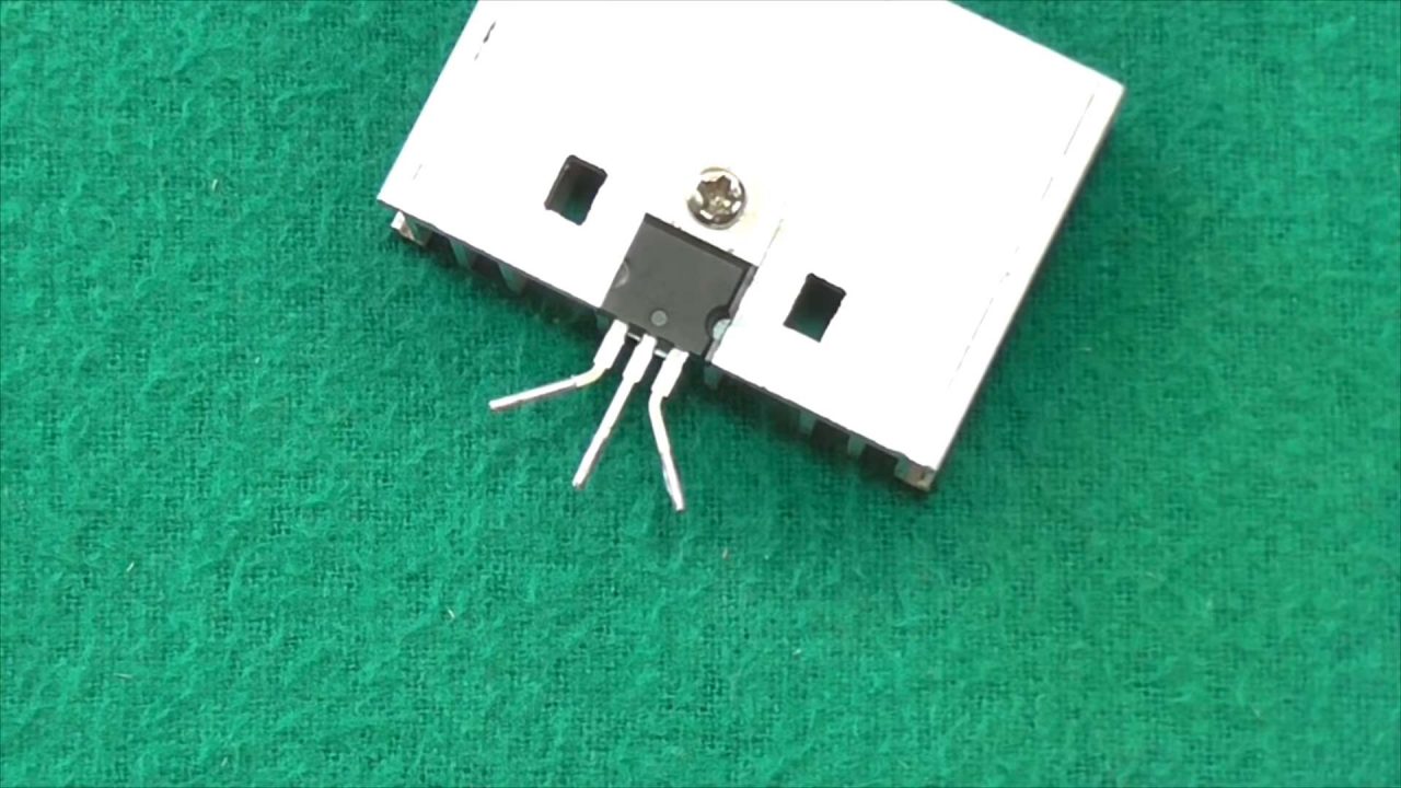
1) Screw on the voltage regulator IC on the heat sink (optional).
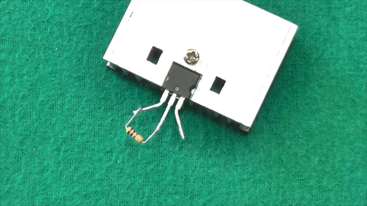
2) Solder a 10K resistor between the Vout & ADJ terminal of the LM317 regulator IC.
3) Solder the +ve terminal of the DC power jack to the Vin terminal of the LM317 IC. After that, Sodler the -ve terminal of the DC power to the fied end/GND of the 10K pot.
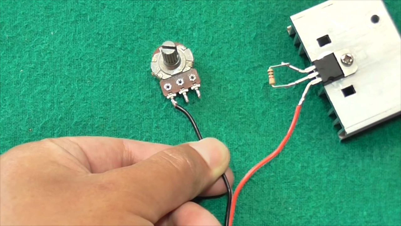
4) After that, solder the wiper terminal of the 10K pot with ADJ pin of the LM317 IC.
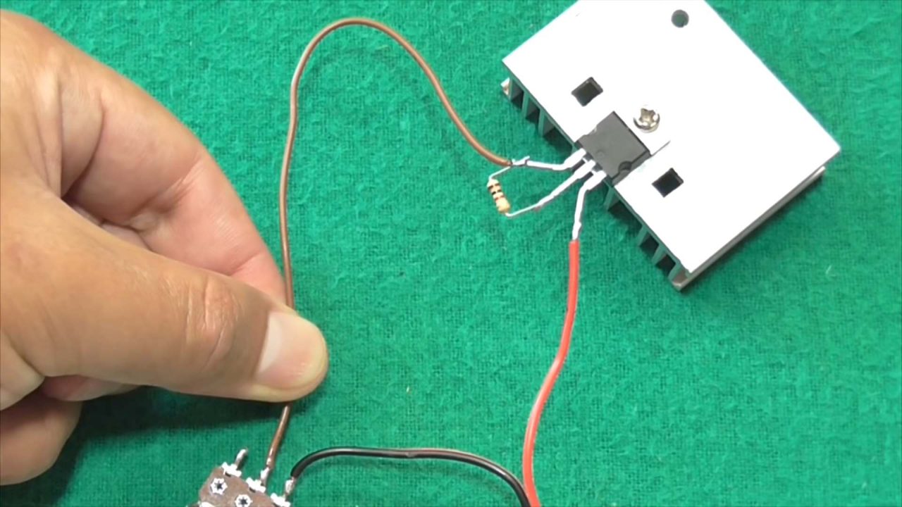
5) Solder the signal/shunt of the digital voltmeter with the Vout pin of the LM317 IC. After that, Solder the Vcc & GND terminals of the voltmeter with the circuits’ Vcc & the GND/fixed end of the 10K pot respectively.

6) Power up & Test the circuit.

Working Explanation
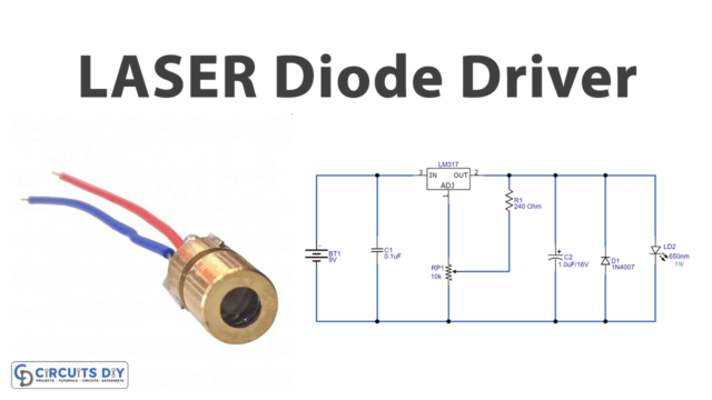
The working of this circuit is very simple. A 220V AC wall adapter is used to translate the 220V input AC to a Rectified 24V – 12V DC signal, which is then fed to the Vin terminal of the LM317 using a DC power jack. This three-terminal voltage regulator has an output voltage operating range from 1.2V to 37V DC with a maximum load current of up to 1.5A. You can tune the output of the regulator IC by connecting a 10K pot between the Vout & ADJ terminal of the IC.
The LM317 IC output is then connected to the signal probe of a voltmeter to display the immediate voltage across any load such as an LED or a DC fan etc.
Applications
- Adjustable Power supplies serve in applications such as powering home appliances, power tools, test bench supplies & trainer board supplies.
- Commonly used in testing small electronic projects.