Introduction
Step right up, folks! Are you ready to experience the thrill of a classic pinball machine without leaving the comfort of your own pocket?
Look no further than this electronic simple pocket pinball game circuit! With just a few simple components, this handheld wonder packs all the excitement and challenge of a full-sized arcade game into a compact and portable device. Sure, it may not have all the bells and whistles of its big brothers, but what it lacks in size, it makes up for in fun. So get ready to tilt, nudge, and flip your way to victory with this super cool electronic pinball game circuit!
Hardware Required
| S no | Components | Value | Qty |
|---|---|---|---|
| 1 | IC | N1…N4 = IC 1 = 4001 FF1, FF2 = IC 2 = 4013 IC 3 = 4017 | 1 1 |
| 3 | Resistor | R1,3 = 1M, R2 = 100K, R4,5,6 = 1K | 2 |
| 4 | Diode | D1…D9 = LED | 1 |
| 5 | Capacitor | 10n | 1 |
| 6 | Switch | – | 1 |
Circuit Diagram
Circuit Explanation
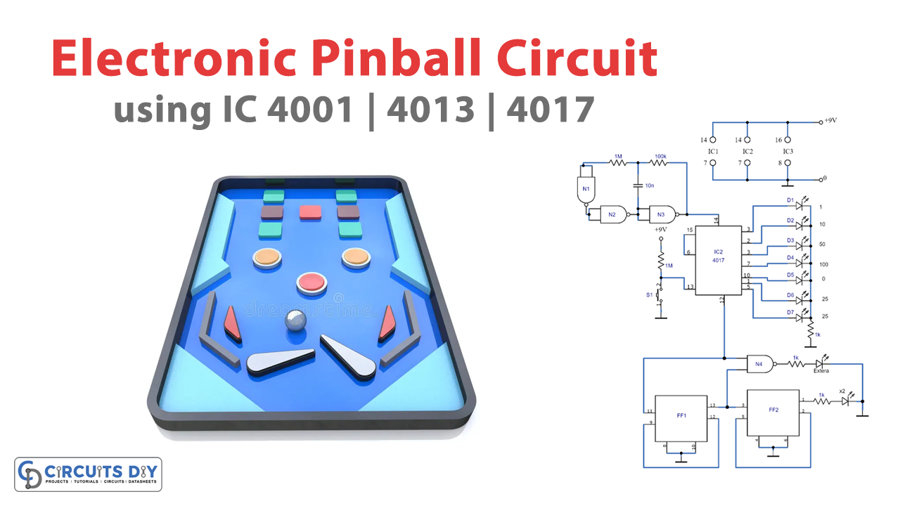
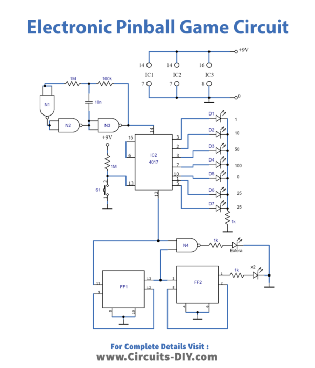
This compact handheld electronic pinball game may not completely replace the larger machines found in amusement arcades, but it is still an enjoyable and entertaining device. The circuitry is relatively straightforward: three CMOS ICs, nine LEDs, six resistors, one capacitor, one push-button, and a 9V battery. The NOR gates N1 to N3 and R1, R2, and C1 form a clock generator that produces a signal applied to the decimal counter IC3. While the player holds down the push-button S1, clock pulses are counted. When the button is released, the counter stops counting, and only one of the LEDs, D1 to D7, will illuminate, indicating the ball’s position.
The carry output of the decimal counter triggers flip-flops FF1 and FF2, which function as 2-bit binary counters. The LEDs D8 and D9 light up depending on the status of the counters. If D8 illuminates, the player earns a free ball, and if D9 lights up their score doubles. This simple circuit doesn’t include a built-in points counter, so players must keep track of their points on paper. The circuit diagram shows the corresponding LED values next to each light. If only one of the LEDs, D5 to D7, lights up, the ball is out of play. If LED D0 illuminates, the ball goes through the middle, and if LED D25 lights up, it goes to the right or left.
With some careful design, the front panel of this electronic pinball game circuit can be arranged so that the LEDs are positioned similarly to a full-sized pinball machine, making the game even more realistic. While it may not be a perfect replacement for a traditional pinball machine, this electronic pocket pinball game is still fun and provides entertainment on the go.
Final Words
We hope you enjoyed learning about this simple electronic pinball game circuit and feel inspired to try building one yourself. With just a few essential components, you can create a fun and challenging game perfect for playing on the go or sharing with friends and family. Remember, the possibilities for customization and personalization are endless, so feel free to get creative and make this project your own. Thank you for reading, and happy gaming!