Introduction
Do your little sibling or your child watches a lot of cartoons on TV that their studies are getting affected? Maybe you have someone in your home that is obsessed with television. Or does your younger brother change the channel while you are watching your favorite series? Or do your uncle watches a lot of political shows every day? Are you experiencing any of these and now you want a solution for that? Hold on! We are here with a creative project that might solve your problem. So, in this tutorial, we are going to create a “TV Remote Signal Jammer Circuit”
But, how does this jammer circuit works? The circuit allows sending a constant IR frequency with the carrier frequency of the transmitter and thus it the receiver gets confused, as a result, doesn’t accept any signal from the remote.
Hardware Required
| S.no | Component | Value | Qty |
|---|---|---|---|
| 1. | IC | NE555 Timer | 1 |
| 2. | NPN Transistor | BC547 | 1 |
| 3. | IR LED | – | 1 |
| 4. | Capacitor | 10nF | 1 |
| 5. | Resistor | 1KΩ, 10KΩ, 220 ohm, 10Ω/1w | 1, 1, 1, 1 |
| . | Potentiometer | 100KΩ | 1 |
| 7. | Battery | 9V | 1 |
| 8. | 2-Pin Connector | – | 1 |
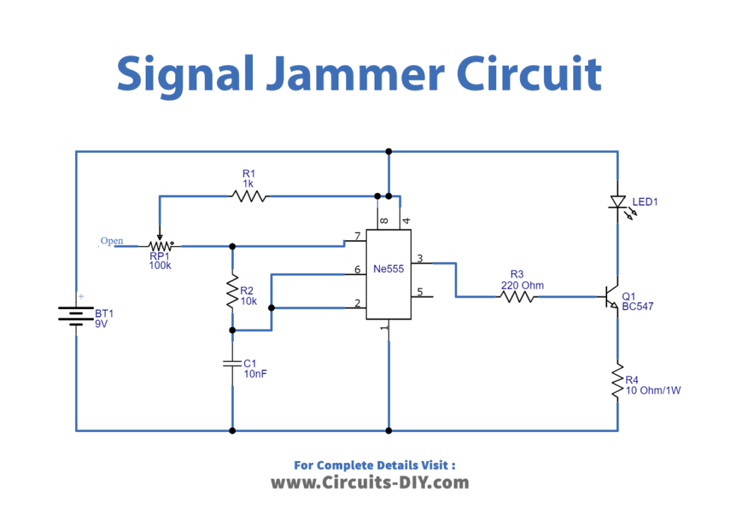
Circuit Diagram
Working Explanation
In this TV Remote Signal Jammer Circuit, IC 555 is utilized as an Astable multivibrator and it will generate square wave pulses in the Range of 32 kHz – 40KHz and can be adjusted by a potentiometer wired in the circuit. Most TV set uses a remote of 38 kHz frequency for communication, but different TV can have a different range of IR frequency. In that case, you need to calibrate this circuit accordingly. There is an IR LED in the circuit which should be placed near the Television
Application and Uses
- As a DIY circuit to jam the IR frequency for television.