A flip-flop circuit’s purpose is to switch ON and OFF an LED or the circuit connected to it by a certain pattern. The circuit here has a mirror-like image having LEDs, transistors, diodes, and relays. This project also operates as a multivibrator circuit.
Hardware Components
The following components are required to make Flip Flop Multivibrator Circuit
| S.no | Component | Value | Qty |
|---|---|---|---|
| 1. | Transistor | 2N4401 | 2 |
| 2. | Diode | 1N4007 | 2 |
| 3. | Resistor | 470Ω, 15KΩ | 2, 2 |
| 4. | Electrolytic capacitor | 47µF | 2 |
| 5. | Relay | 12V | 2 |
| 6. | Battery | 9V-12V | |
| 7. | LED | – | 2 |
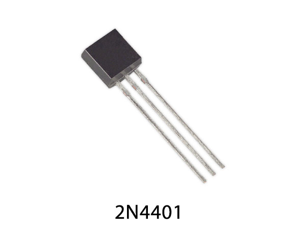
2N4401 Pinout
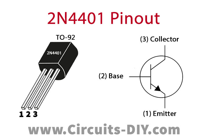
For a detailed description of pinout, dimension features, and specifications download the datasheet of 2N4401
Flip-Flop Multivibrator Circuit
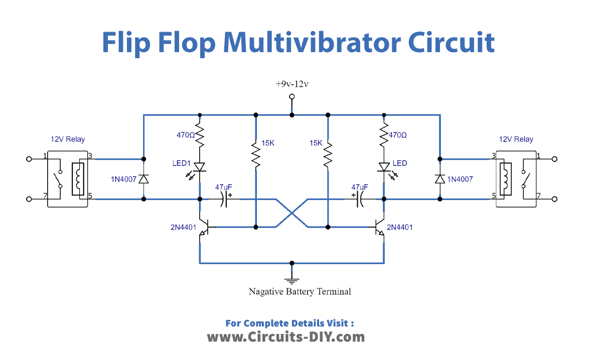
Working Explanation
In this circuit, two NPN transistors 2N4401 are working as switches. For the prevention of back EMF to the two relays, diodes 1N4007 are connected with them. The resistors R2 and R3 control the switching mechanism of both the LEDs and relays. The duration of switching ON and OFF depends on the value of these resistors. Furthermore, decreasing the value of R2 and R3 resistors increases the time duration for which LEDs and relays are turned ON or OFF. Moreover, the resistor R1 and R4 plays the part of the current limiting component for the LEDs attached to the circuit. The relay in the circuit connects external electronic circuits to this one and hence, electronic circuits are controlled.
The operating voltage of the circuit is 12V maximum but is also operational at 5V-6V. In this case, the relays are selected such that the voltage rating is the same as the battery power supply.
Application
- Home appliances times based on flip flop function.
- Events counter/game counter