
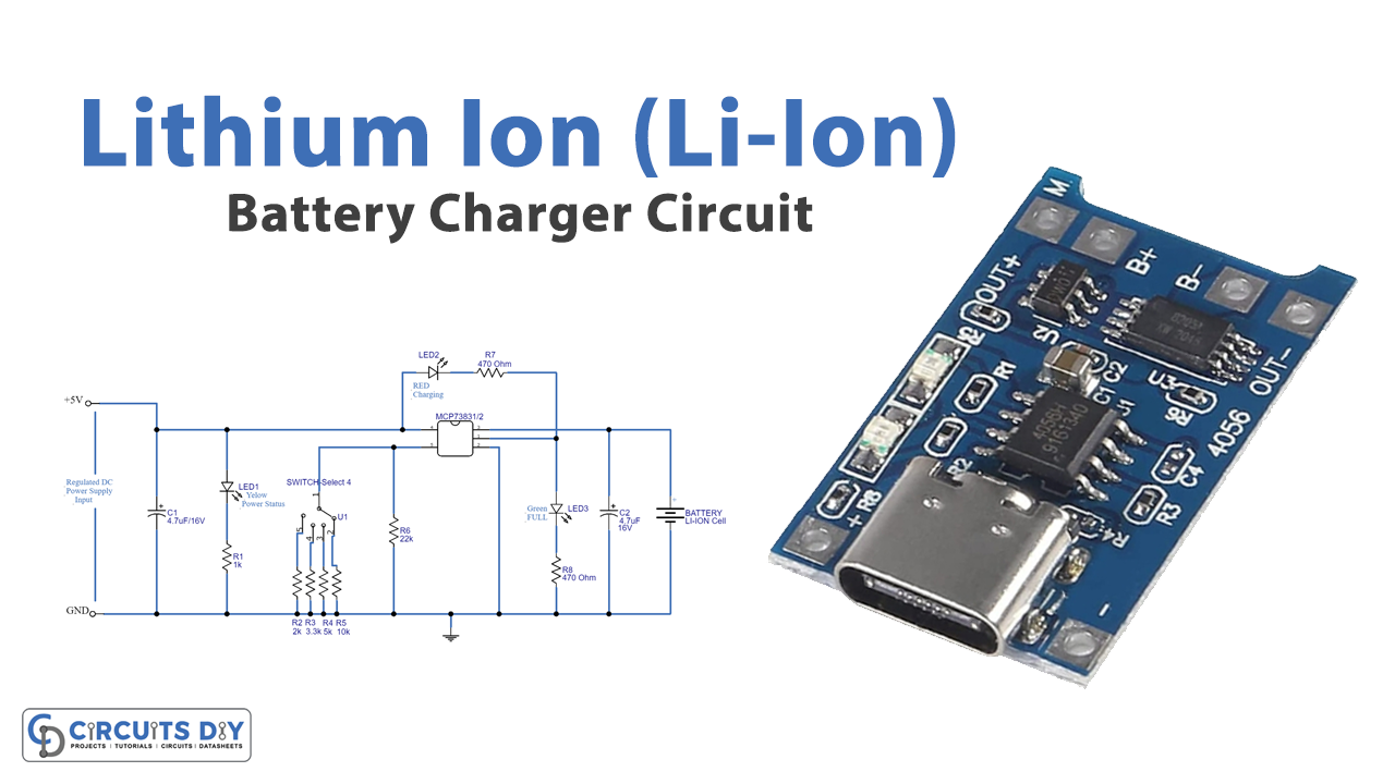
In this tutorial, we are going to make a “Li-Ion Battery Charger Circuit”. Lithium-based batteries are a flexible method for storing a high amount of energy. They have one of the most elevated energy densities and specific energy (360 – 900 kJ/kg), as compared to other rechargeable batteries. Unlike, a lead-acid battery, a Li-Ion battery can be charged at significantly high initial currents. Which can be as high as the Ah rating of the battery itself. This is termed as charging at a 1C rate, where C is the Ah value of the battery. Having said this, it is never advisable to use this extreme rate, as this would mean charging the battery under highly stressful conditions due to an increase in its temperature.
These batteries are very much prone to overcharge or charging with high voltage or high current. Here we design a simple easy to construct Li-Ion battery charger circuit by using IC MCP73831/2 from the microchip. This is a miniature single-cell fully integrated li-ion and li-polymer charge management controller. It is available in a tiny package, hence most suitable for compact handheld and portable applications. This MCP73831/2 IC will give constant current and constant voltage for charging the battery. Also, the voltage range and current value can be changed. The output voltage range can be fixed with four available options 4.20V, 4.35V, 4.40V, or 4.50V. And the current value can be varied by using an external resistor connected to the PROG pin.
Hardware Required
| S.no | Component | Value | Qty |
|---|---|---|---|
| 1. | IC | MCP73831/2 | 1 |
| 2. | Switch-Select-4 | – | 1 |
| 3. | LED | – | 2 |
| 4. | Resistor | 1KΩ,22KΩ,470Ω,2KΩ,3.3KΩ,5KΩ,10KΩ | 1,1,2,1,1,1 |
| 5. | Capacitor | 4.7uf/16V | 2 |
| 6. | Connecting Wires | – | – |
| 7. | Power Supply | 5V | 1 |
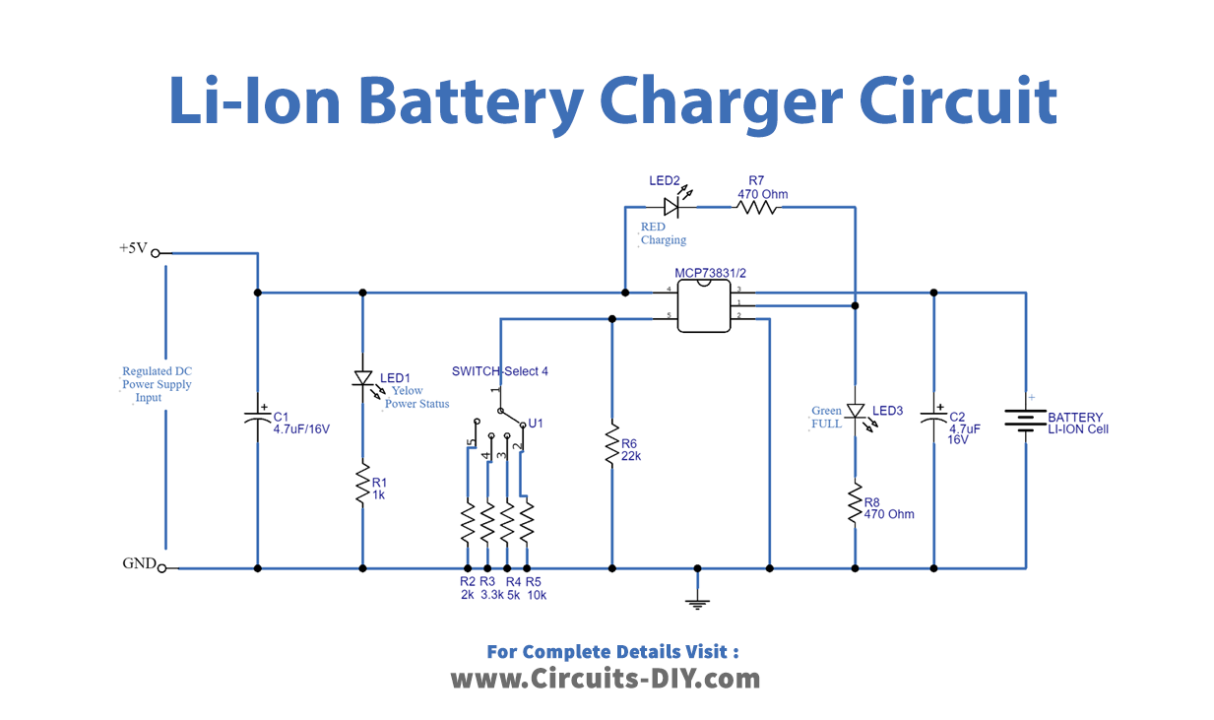
Circuit Diagram
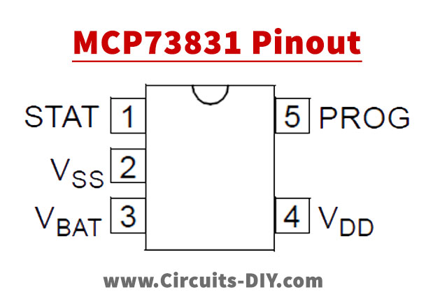
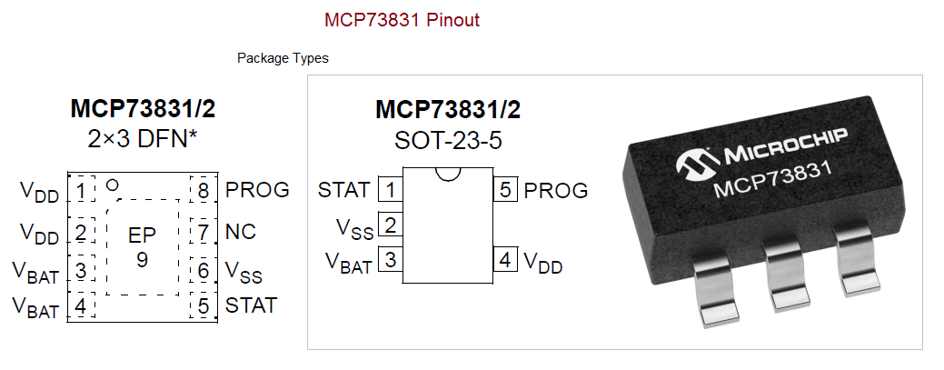
MCP73831/2 Pinout
Working Explanation
This circuit is constructed to charge the Li-Ion battery cell with variable current output. As shown in the circuit, the four-terminal select switch is employed to change the charging current. Here as we have used IC MCP73831/2, this IC employs a constant current/constant voltage charge algorithm with selectable preconditioning and charge termination. A regulated 5V DC power supply is applied to the charge controller’s VDD pin. C1 capacitor performs filter operation and LED1 provides the input power source status. Different value resistors (2KΩ, 3.3Ω, 5KΩ, and 10KΩ) are connected to the four-terminal select switch and the common terminal is connected to the PROG pin. By selecting different resistors, we can get different value charging currents (15mA to 500mA). Pin 1 (STAT) is output for connection to an LED for charge status indication. Alternatively, a pull-up resistor can be applied for interfacing with a host microcontroller. STAT is a tri-state logic output on the MCP73831 and an open-drain output on the MCP73832. Pin 2 (VSS) is
connected to the negative terminal of the battery. Pin 3 (VBAT) is
connected to the positive terminal of the battery. The drain terminal of the internal P-channel MOSFET pass transistor. Bypass to VSS with a minimum of 4.7 µF to ensure loop stability, when the battery is disconnected. Pin 4 (VDD) is a battery management input supply, a supply voltage of [VREG (typical) + 0.3V] to 6V is recommended. Bypass to VSS with a minimum of 4.7 µF. Pin 5(PROG) is a current regulation set, here preconditioning, fast charge, and termination currents are scaled by placing a resistor from PROG to VSS. The charge management controller can be disabled by allowing the PROG input to float.
Now LED2 indicates the battery charging status and LED3 glows if the charging battery becomes full. Target Li-Ion battery connected between Pin3 and ground.
Application
The main application of this circuit is used to charge the Li-ion batteries.


