Introduction
If you have ever left a lead-acid battery unused for a long time, you may have found it dead or damaged when you tried to use it again. Fortunately, there is a simple and effective solution to this problem: a self-regulating battery charger circuit. This circuit can help maintain your battery’s health during periods of dormancy, ensuring it remains fully functional when needed.
In this tutorial, we will make this self-regulating charger circuit. So let’s dive in
Hardware Required
| S no | Components | Value | Qty |
|---|---|---|---|
| 1 | Transformer | 12V 5A | 1 |
| 2 | Fuse | 10 A T | 1 |
| 3 | Resistor | 10k, 68 | 1, 1 |
| 4 | Diode | 1N4007 | 1 |
| 5 | Bridge Ractifier | B040C10000 | 1 |
| 6 | Transistor | 2n2222, BC547B | 1, 1 |
| 7 | Zener Diode | 12V 400mW | 1 |
| 8 | LED | Red | 1 |
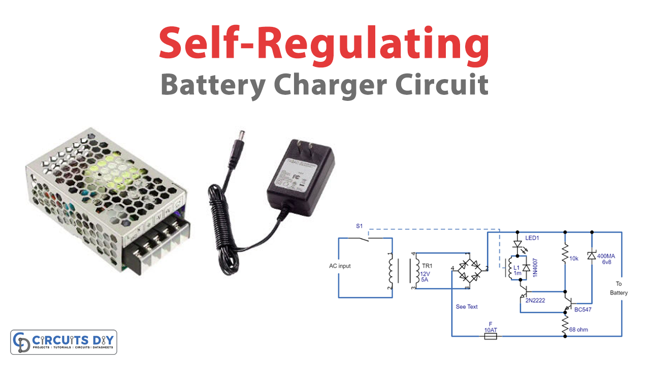
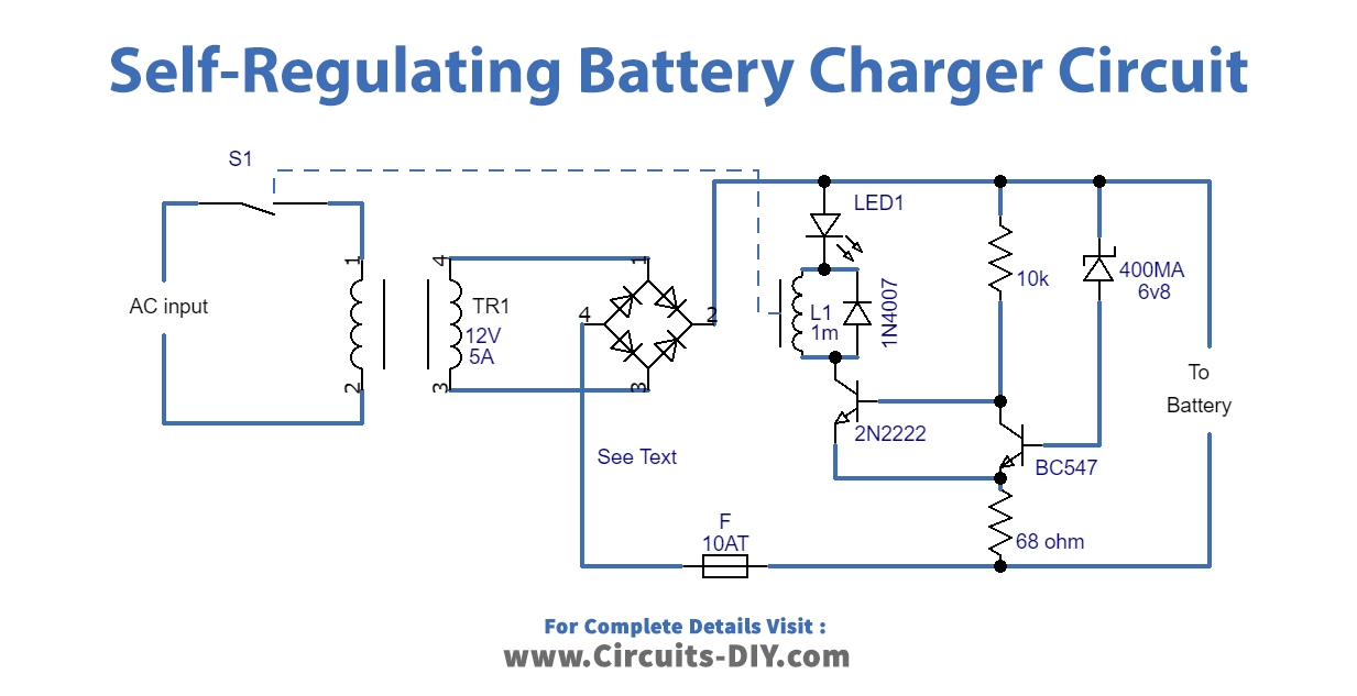
Circuit Diagram
Working of Self-Regulating Battery Charger Circuit
The self-regulating battery charger circuit operates on a Schmitt trigger T1/T2. The circuit charges the battery and then allows it to discharge through itself and the internal resistance of the battery. Once the charge level drops below a certain point, the circuit automatically charges the battery again. This process continues in a cycle, ensuring the battery is always kept at an optimal charge level.
Testing the Circuit
You can test the self-regulating battery charger circuit by applying 13.6 V and 12.5 V voltages across the battery terminals without the mains or any battery connected to it. If the circuit works correctly, the relay should switch off and on, respectively. You can adjust the circuit by connecting a 1N4148 (cathode to + line) to D7 in series and varying R2, such as by using a fixed 100 Ω resistance in its place.
Charging Two Batteries in Series
The self-regulating battery charger circuit can also be used to maintain two 12 V batteries by automatically regulating their charging voltage. To achieve this, you need to raise the main transformer secondary voltage, the D7 zener voltage, the relay coil voltage, and the hysteresis. Once you have made these adjustments, you can fit both batteries across the terminals in series. The circuit is protected against short circuits using a fuse.
Important Considerations
It is worth noting that the self-regulating battery charger circuit will not work with a fully discharged battery. The battery must be charged over 10 V for the circuit to function correctly.
Conclusion
The self-regulating battery charger circuit is a straightforward and efficient solution to the problem of battery degradation due to prolonged periods of dormancy. The circuit is easy to implement and adjust, making it an excellent choice for anyone looking to maintain their battery’s health. Moreover, the circuit is designed with safety in mind and is protected against short circuits, ensuring you can use it confidently.
Final Words
The self-regulating battery charger circuit is a straightforward and efficient solution to the problem of battery degradation due to prolonged periods of dormancy. The circuit is easy to set up and adjust, which makes it an excellent choice for anyone who wants to keep their battery in good shape. Moreover, the circuit is designed with safety in mind and is protected against short circuits, ensuring you can use it confidently. Try out this circuit, and for any queries, feel free to comment. Happy building!