In this project, we are making a Battery Monitor circuit. When we do projects related to batteries or power supply, we always have a dare. We know that the battery did not load or offload. There is a method for battery checking, which is possible with a voltmeter. Still, the battery controller was built to test battery charging. By linking batteries to the circuit, we can quickly check batteries. Some battery status LEDs are used to display.
Hardware Component
The following components are required to make Battery Monitor Circuit
| S.no | Component | Value | Qty |
|---|---|---|---|
| 1. | Op-amp IC | LM358 | 2 |
| 2. | Battery | 9v | 1 |
| 3. | Potentiometer | 10K | 4 |
| 4. | Breadboard | – | 1 |
| 5. | Battery Connector | – | 1 |
| 6. | LED | – | 4 |
| 7. | Resistor | 10K, 220 Ohm | 1, 4 |
LM358 Pinout
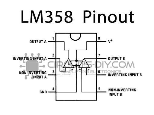
For a detailed description of pinout, dimension features, and specifications download the datasheet of LM358
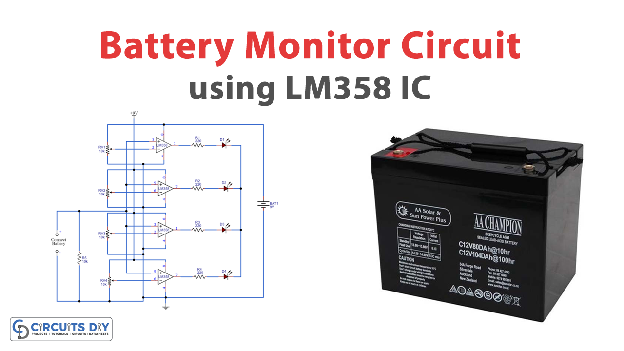
Battery Monitor Circuit
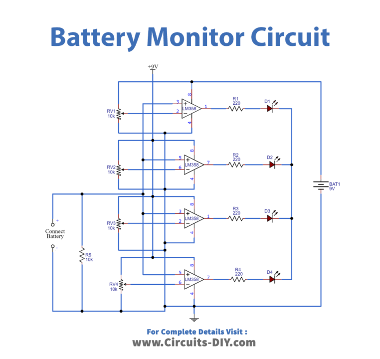
Working Explanation
In this battery monitor circuit, two dual comparator ICs were used for comparing voltages. The non-invert and 10 K potentiometer are a link to the inverter end and the positive terminal wire protester battery. The non-inverting pins of both comparators are connected. In a resistor of 220 ohms, there are four green LEDs linked to the battery power pins. A 9-volt battery or converter which use to power the circuit.
Applications and Uses
This battery level monitor circuit can be used in a 12 Volt Lead Acid battery or in tubular batteries to show the charging system. If the battery accepts the charge or not, the LED status shows.