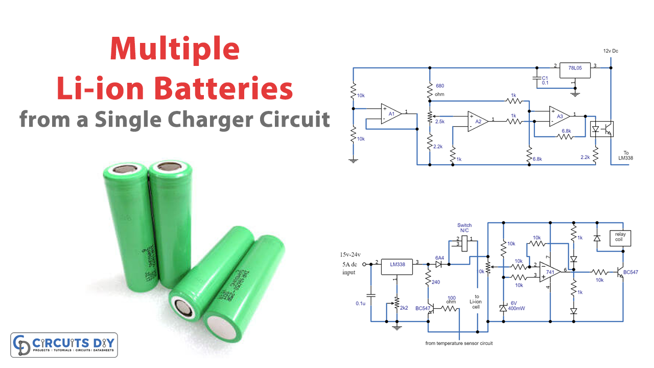
Introduction
Are you tired of charging each Li-ion battery individually and taking up all your time? Look no further because we have a solution for you! With our easy circuit, you can now charge a minimum of 25 Li-ion cells collectively in no time from a single voltage source or a 12V battery. We understand the importance of following strict guidelines when it comes to charging Li-ion cells, and we have designed a circuit that not only charges the cells at a full 1C rate but also ensures proper heat management to avoid any potential damage or explosion.
Our circuit includes an accurate temperature sensor circuit that detects heat from the cells and controls the charging current if the heat deviates from safe levels. So, say goodbye to the hassle of charging each Li-ion battery individually and embrace the convenience of our automatic Li-Ion cell charger and controller circuit.
Circuit Diagram
Managing Li-ion Battery Charging Heat Circuit
Hardware Table
| S.no | Components | Value | Qty |
|---|---|---|---|
| 1 | IC | A1, A2, A3 = LM324 | 1 |
| 2 | Voltage Regulator | 78L05 | 1 |
| 4 | Transistor | BC547 | 1 |
| 5 | Capacitor | 0.1uF | 1 |
| 6 | Resistor | 10k, 680, 2.2k, 1k, 6.8k | 2, 1, 2, 3, 2 |
| 7 | V. Resistor | 2.5k | 1 |
| 8 | Diode | 1N4148 | 1 |
| 9 | LED | Green | 1 |
Automatic Li-Ion Cell Charger and Controller Circuit
Hardware Table
| S.no | Components | Value | Qty |
|---|---|---|---|
| 1 | IC | 741 | 1 |
| 2 | Voltage Regulator | LM-338 | 1 |
| 3 | Relay | 12V | 1 |
| 4 | Transistor | BC547 | 2 |
| 5 | Capacitor | 0.1uF | 1 |
| 6 | Resistor | 240, 100, 10k, 1k | 1, 1, 5, 2 |
| 7 | V. Resistor | 2K2, 10k | 1, 1 |
| 8 | Switch | – | 1 |
| 9 | LED | Green, Red | 1, 1 |
| 10 | Diode | 6A4 | 1 |
| 11 | Zener Diode | 6V 400mW | 1 |
Circuit Explanation
One advantage of Li-ion batteries is that they can initially be charged at a full 1C rate, unlike lead acid batteries, which only allow a maximum charging rate of C/5. This advantage enables Li-ion batteries to be charged at a rate that is 10 times faster than lead-acid batteries.
Effective management of heat is crucial and can simplify everything else. This enables us to charge Li-ion cells at a full 1C rate without any concerns as long as we have a mechanism in place that monitors heat generation from the cells and implements corrective measures if necessary.
To address this, we have incorporated a separate heat detection circuit that detects the cells’ temperature and regulates the charging current if the temperature exceeds safe limits.
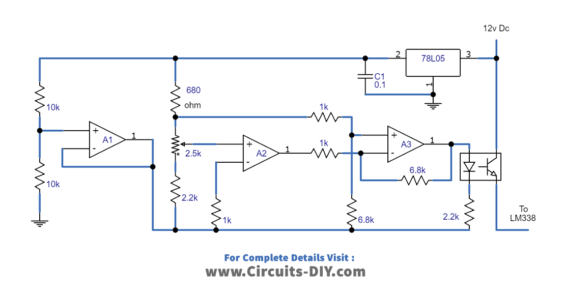
Circuit For Managing Li-ion Battery Charging Heat (Figure 1)
The first schematic diagram ( above in the circuit diagram section) displays an accurate temperature-sensing circuit that takes advantage of the LM324 IC. Three of its opamps are utilized in this design.
In this case, the iN4148 diode functions as an efficient temperature sensor, where its voltage drops by 2mV with each degree increase in temperature. This shift in voltage across D1 prompts A2 to alter its logical output, which is connected to A3, slowly increasing its output voltage in a similar manner.
The opto coupler LED is linked to the output of A3. Depending on the setting of P1, the output of A4 tends to increase in response to the heat emitted by the cell until the LED connected to it lights up, and the opto transistor becomes active. Then, the opto transistor supplies the LM338 circuit with the required 12V to initiate the necessary corrective measures.
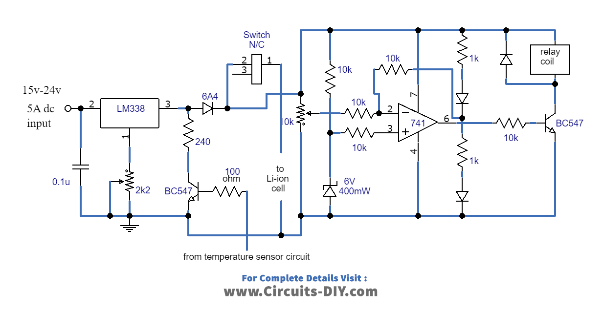
Automatic Li-Ion Cell Charger and Controller Circuit (Figure 2)
Using the IC LM338, the second circuit illustrates a simple controlled power supply that adjusts the 2k2 pot to produce precisely 4.5V across the Li-ion cells. The previous IC741 circuit functions as an overcharge cut-off circuit that manages the cell charge and disconnects the power supply when it exceeds 4.2V. To ensure that the cells do not overheat, the BC547 on the left side of the ICLM338 is utilized to implement appropriate corrective measures.
If the cells become too hot, the temperature sensor optocoupler provides the LM338 transistor (BC547) with power, causing it to stop and instantly turn off the LM338 output until the temperature drops to normal levels. This process continues until the cells are fully charged, at which point the IC 741 is triggered, and the cells are entirely disconnected from the power source.
To ensure even charge distribution, every positive line of the circuit in parallel with 25 cells must have a diode and a 5 Ohm 1-watt resistor added. We must securely place the package containing all the cells on an aluminium platform for equal heat dissipation across the plate. Proper placement of sensor D1 over the aluminium plate is crucial for optimal heat dissipation.
Final Thoughts
In conclusion, our automatic Li-Ion cell charger and controller circuit is a game-changer when it comes to charging multiple Li-ion batteries collectively. With its advanced temperature sensor circuit and controlled power supply, you can trust that you will charge your Li-ion cells safely and efficiently. The circuit is designed to charge the cells at a full 1C rate while ensuring proper heat management, which is crucial for the safety of the cells.
So, if you are tired of wasting your time charging each Li-ion battery individually, give our circuit a try and experience the convenience and efficiency of charging multiple Li-ion cells from a single charger circuit. Happy building!