What is a Cell Phone Detector?
A Cell phone detector basically senses the presence of any cellular device within its vicinity & provides a relevant indication. It can also be considered as a frequency detector or a current-to-voltage converter. With the current trend in technological advancement, the use of cellular devices such as mobile phones & smartphones has increased ten folds. Cell phone detectors scan frequency ranges of about 0.8 – 3.0GHz, making them an ideal choice for environments in which using mobile phones is prohibited such as military installments. So, in today’s tutorial, we will go through a step-by-step procedure on how to build a Cell Phone Detector using LM358 Op-Amp IC.
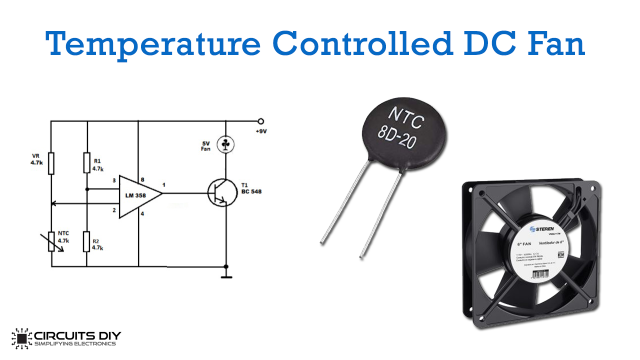
The main component of this circuit is an LM358 IC. LM358 is a dual op-amp IC integrated with two op-amps powered by a common power supply. It can be considered as one-half of the LM324 Quad op-amp which contains four op-amps with a common power supply.
Hardware Components
The following components are required to make a Cell Phone Detector Circuit
| S.no | Component | Value | Qty |
|---|---|---|---|
| 1. | Op-Amp IC | LM358 | 1 |
| 2. | Buzzer | 5V | 1 |
| 3. | LED | 5mm/3.5V | 1 |
| 4. | Cell Phone Detector PCB | – | 1 |
| 5. | Enameled Copper Wire | – | 3m/25 AWG |
| 6. | Potentiometer | 10K | 1 |
| 7. | Capacitor | 100nF | 3 |
| 8. | Resistor | 6.8M, 1K | 4 |
| 9. | Soldering Iron | 45W – 65W | 1 |
| 10. | Soldering Wire with Flux | – | 1 |
| 11. | DC Battery | 9V | 1 |
| 12. | Battery Clip | – | 1 |
LM358 Pinout
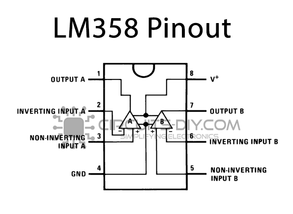
For a detailed description of pinout, dimension features, and specifications download the datasheet of LM358
Useful Steps
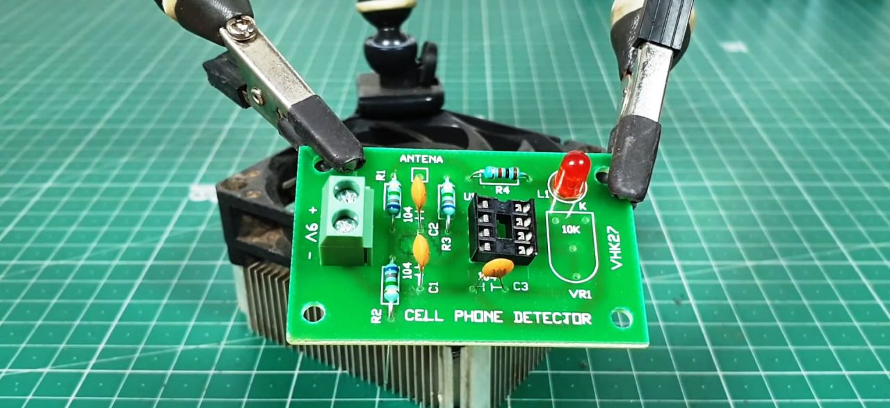
1) Solder the output block connector & resistors on the PCB board.
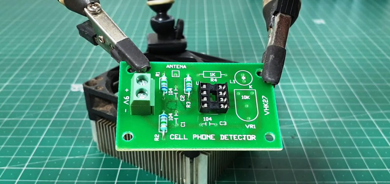
2) Solder the 100nF Capacitors & the LED on the PCB board.
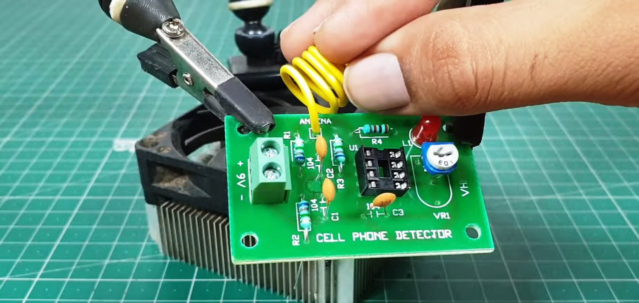
3) Solder the 10K pot & the antenna on the PCB board.
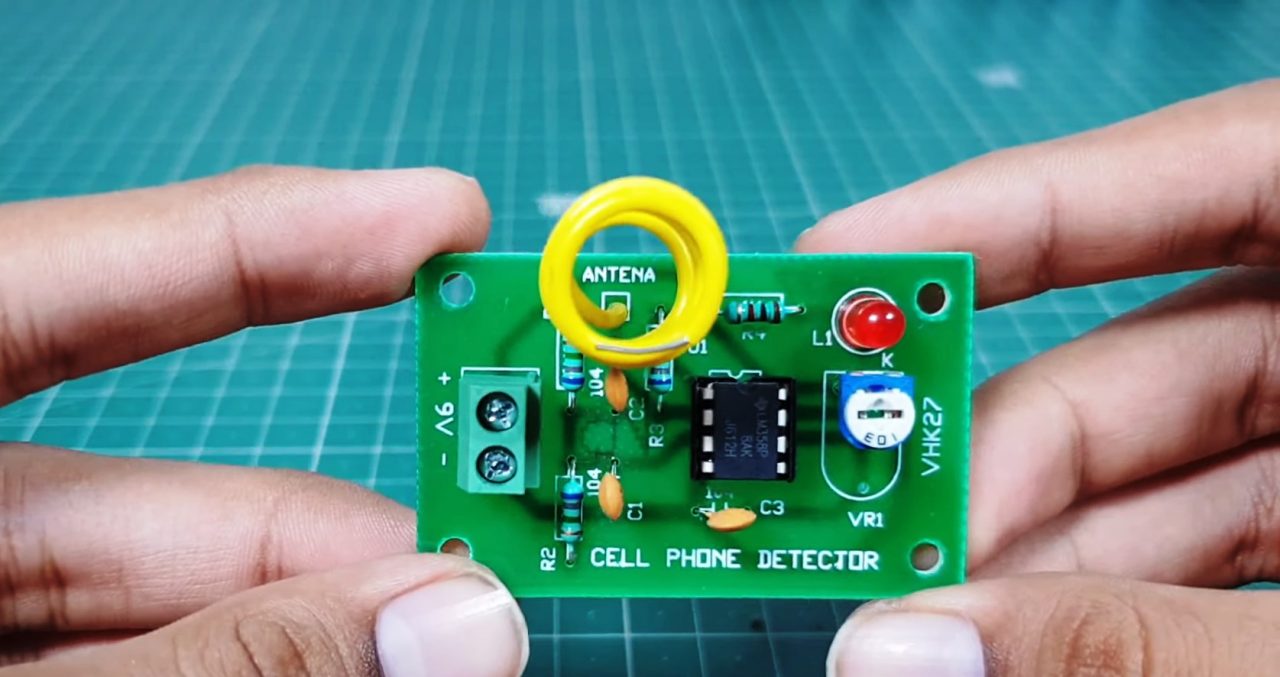
4) Solder the LM358 IC on the PCB board.
5) After that tune the preset pot. Now power up & test the circuit.

Working Explanation
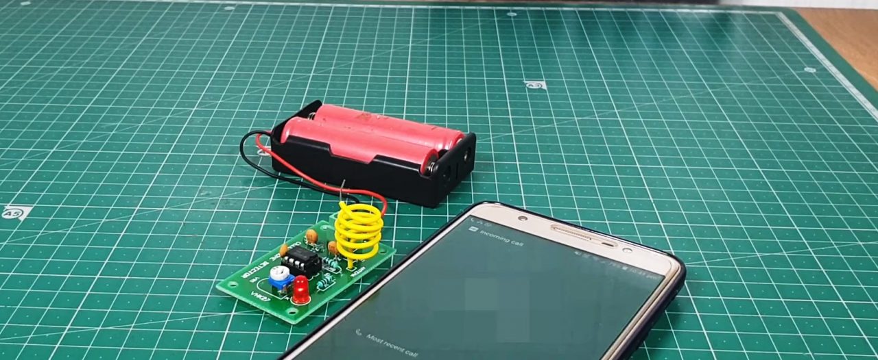
This cell phone detector can sense the activity of any cellular device whilst transmitting. When a call or SMS is sent from the cell the circuit antenna detects the RF signal through mutual induction & forwards a signal to the inverting input of the LM358 op-amp IC.
The op-amp IC amplifies the input signal & triggers the LED & the buzzer to operate, indicating the presence of cell phone signals in the surrounding area. You can use a 5V – 9V battery to power up the circuit.
Application
- Generally functions in areas where the use of a cellular device is prohibited such as military installments & ATC testing sites.