In this tutorial, we are going to make an “Automatic battery charger circuit”.
A battery charger is a device that stores energy in a battery by running an electric current through it. If you are using a Lead-Acid Battery and need a long life of it, you should use an Automatic battery charger circuit. This auto-turn-off battery charger automatically disconnects from the mains to stop charging when the batteries are fully charged. It can be used to charge partially discharged cells as well. The circuit is simple and can be divided into an AC-to-DC converter, relay driver, and charging sections.
Hardware Components
The following components are required to make Automatic Battery Charger Circuit
| S.no | Components | Value | Qty |
|---|---|---|---|
| 1. | Resistors | 2K, 1.5K, 10K, 560 ohms | 2, 1, 1, 1 |
| 2. | Potentiometer | 10K | 1 |
| 3. | Electrolytic Capacitor | 100uF | 1 |
| 4. | SCR | 2N6397, 2N5060 | 1, 1 |
| 5. | Zener Diode | 6.8V | 1 |
| 6. | Diode | 1N5404, 1N4002 | 2, 1 |
| 7. | LED | – | 1 |
| 8. | PCB | – | 1 |
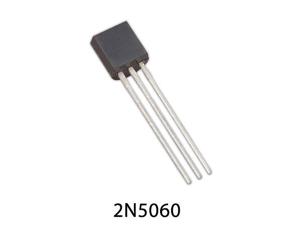
2N5060 SCR Pinout
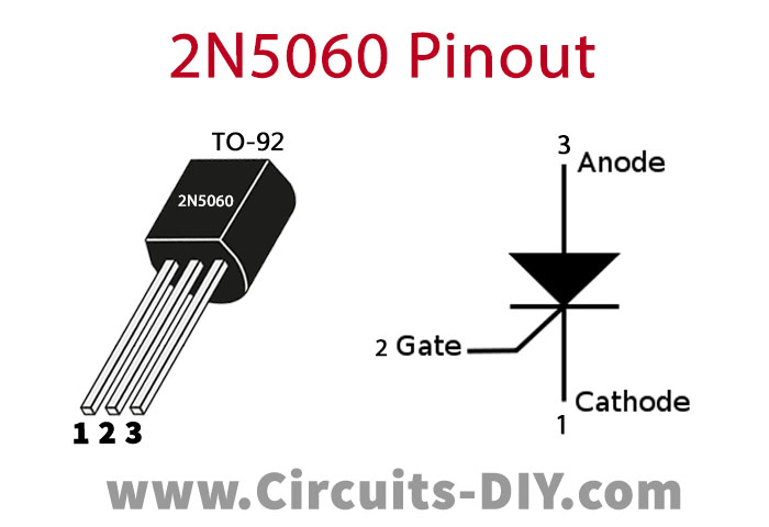
For a detailed description of pinout, dimension features, and specifications download the datasheet of 2N5060
2N6397 Pinout
For a detailed description of pinout, dimension features, and specifications download the datasheet of 2N6397
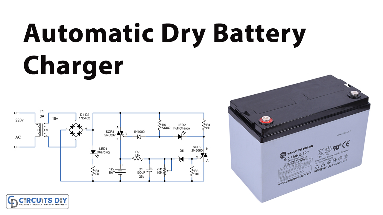
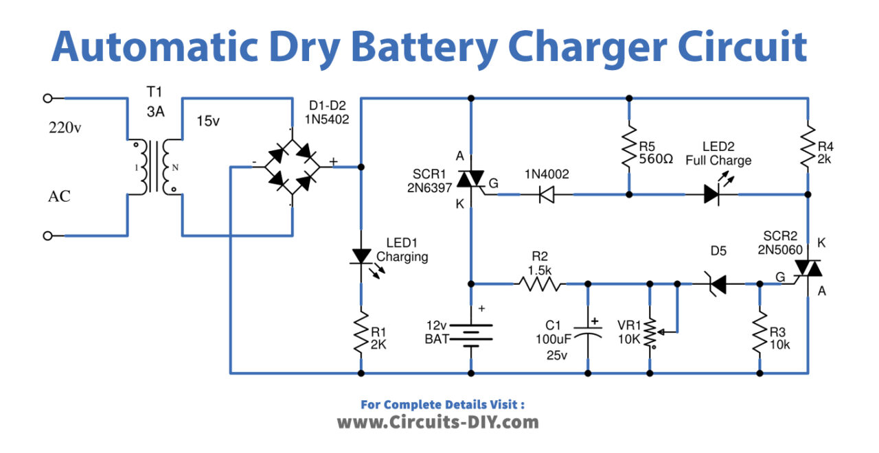
Automatic Battery Charger Circuit
Working Explanation
As shown in the circuit. First, an AC 220V will flow to a transformer to transform to 15 volts. These 15v signals are fed to a full-wave bridge rectifier, which converts AC into DC. The LED1 is for the power indicator.
Then SCR1 will start working. The DC 15V will flow to R3, which is used to limit or decrease the current flow through diode D5. D5 protects the reverse voltage before bias to lead G of SCR1.
When SCR1 conducts, 15V flows through lead K to a positive battery terminal. Ideally, SCR1 will conduct current and stop current alternately very fast with a frequency of 100 Hz. The output frequency of a full-wave rectifier is 50Hz+50Hz. The current of this feature is a continuous positive half of the sine wave. It is different from the voltage with the capacitor filter, which is smooth as a straight line.
So SCR1 does not conduct the current all time. When there is a positive voltage to bias at lead G. Since the waveform of voltage is DC pulse, not smooth. The SCR will stop conducting current. If disconnecting is not a positive voltage. Then, the positive voltage waveform comes to SCR1 again. It will start conducting currents again, this was reversed with a frequency of 100Hz.
To begin with, the positive battery voltage flows through R2 to reduce current. And, C1 will filter a current to smooth. Second, the current flows through VR1 to divide voltage down. Then, the Zener diode-ZD1 pass an overvoltage to bias lead G of SCR2. We adjust a level of VR1 to set a full battery. Until voltage at negative of ZD1 is more than 6.8V or about 7.3V.
After that, ZD1’s saturation voltage collapse flow to feeds lead G of SCR2. It causes SCR2 to conduct current. R4 is used for SCR2 extraordinary stable work. When SCR2 works, causes negative voltage flows to lead K to A. It results in an LED2 glow. And the same time SCR1 will stop conducting current.
Pinout of TO-220 and TO-92 of SCRs, since lead G of SCR1, get negative voltage from SCR2 there. In the case of the battery, a lower voltage causes the voltage at negative of ZD1 is lower than 6.8V. It makes lead G of SCR2 not get positive voltage. But it can get only negative voltage through R4, result SCR2 does not conduct current.