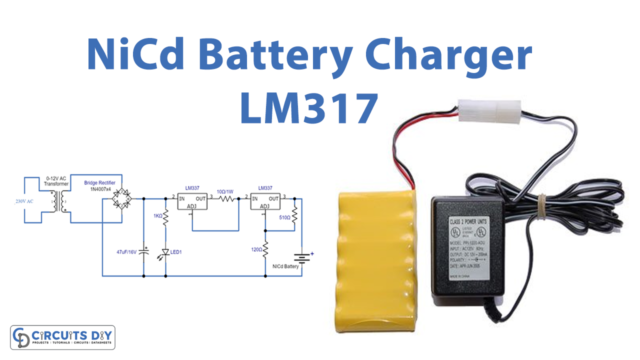
In this tutorial, we are going to make a “Solar battery charger with overcharge protection”.
The energy from a solar cell or a solar panel should be effectively stored so that it can be used as per one’s preference, normally after the sun has set or when it’s dark and when the stored power becomes much needed for operating the lights. Voltage from a solar panel can vary hugely, depending upon the incident sun rays, and the current also varies. Rechargeable batteries are probably the best and the most efficient way of collecting or storing electrical energy for later usage. And these batteries need to be protected from overcharging.
Hardware Components
The following components are required to make Solar Battery Charger Circuit
| S.no | Component | Value | Qty |
|---|---|---|---|
| 1. | Solar Cell | – | 1 |
| 2. | Resistors | 22K, 8.2K, 5 ohms, 68 ohms, 0.5 ohms | 1 |
| 3. | Diode | IN4002 | 1 |
| 4. | Zener Diode | IN5821, IN753A | 1, 1 |
| 5. | Transistor | MJ1000 | 1 |
| 6. | Potentiometer | 20K | 1 |
| 7. | Capacitor | 22uf | 1 |
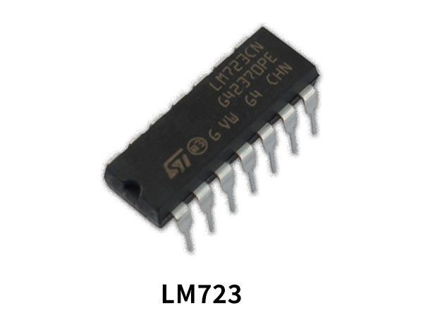
| 8. | IC | LM723 | 1 |
LM723 Pinout
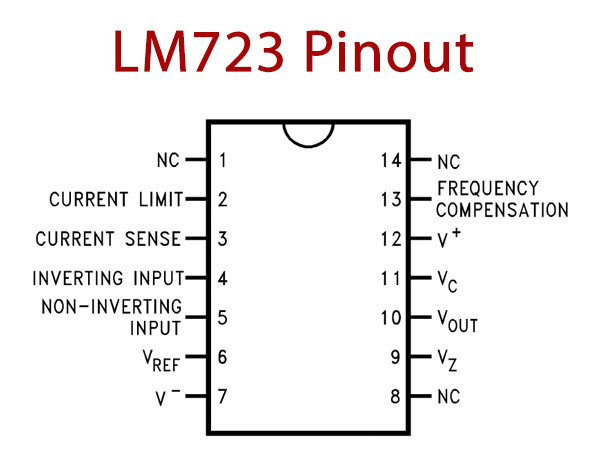
For a detailed description of pinout, dimension features, and specifications download the datasheet of LM723
Solar Battery Charger Circuit
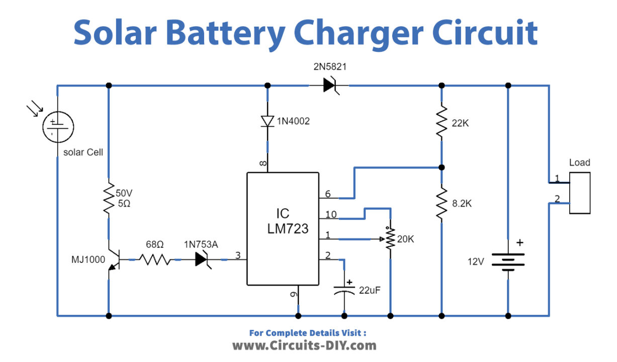
Working Explanation
This circuit is formed in a way that it can maintain one position voltage from a solar cell with a shunt regulator circuit. It protects the battery from over-voltage. This circuit has IC LM723 as the main part if you are using battery model acid general lead. Then you need a power supply all the time from the circuit. Thus, one should choose a battery that has a capacity such as 40Ah.
LM723 IC is a voltage regulator but it can generate a variable voltage that can be adjusted in a range of 3V to 37V. It offers a 150mA output current. The maximum input voltage supply is 40V.
An input voltage is applied to the PIN12 of LM723 to get a constant and regulated output voltage at Pin10. Now, power is fed to LM723 from the base of the transistor through resistor R2 and Zener diode D3 at (PIN9) Vz. To adjust the output voltage value, the non-inverting pin is connected with a potentiometer. Vref of LM723 is adjusted with R3/R4. PIN13 is used to reduce noise in a circuit by connecting a capacitor with it. The diode D2 is to protect the current flow turn back from the battery during nighttime.
Applications
This circuit can be used to charge home devices and vehicle batteries such as cars, boats, RVs, and more.