In this tutorial, we are going to make a “NiCd Battery Charger Circuit”.
To charge batteries, we need to put a voltage across the terminals, and the battery starts charging. The charging protocol depends on the size and type of the battery being charged. Some battery types have a high tolerance for overcharging and can be recharged by connection to a constant voltage source or a constant current source, depending on the battery type. If safe charging, fast charging, and/or maximum battery life are important, that’s when things get complicated.
Here we have the three most common batteries in electronic devices NiMH, NiCd, and Li-ion. In these batteries, the C rate is an important consideration when defining charging parameters. “C” refers to the battery’s capacity when discharged over one hour. The capacity of these batteries is determined relative to the minimum allowable voltage, called the cut-off voltage. It is this voltage that generally defines the “empty” state of the battery. At that point, there is still a charge left, but drawing it out risks damaging the battery.
If you are looking for batteries for your project that can charge easily and fast. Then, consider getting a Ni-Cd battery. Also, the Ni-Cd battery packs are more tolerant and perform under harsh conditions. Further, the battery is more durable than lithium batteries or lead-acid batteries. And the device has high energy, like alkaline batteries. NiCd batteries provide better performance in a compact size. Simple NiCd Battery charger circuit made with few easily available components. This circuit will provide limited current and voltage to the target battery.
Hardware Components
The following components are required to make NiCd Battery Charger Circuit
| S.no | Component | Value | Qty |
|---|---|---|---|
| 1. | Step Down Transformer | 0-12V AC | 1 |
| 2. | Bridge Rectifier Module | 1N4007 | 4 |
| 3. | Regulator IC | LM337 | 2 |
| 4. | Resistor | 1KΩ, 120Ω, 510Ω, 10Ω/1W | 1 |
| 5. | LED | – | 1 |
| 6. | Capacitor | 47µF/16V | 1 |
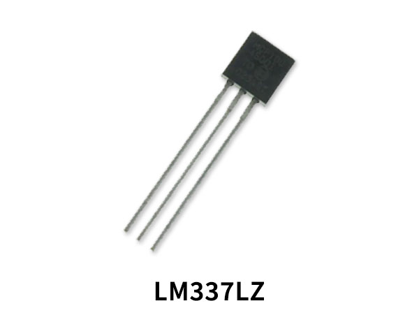
LM337 Pinout
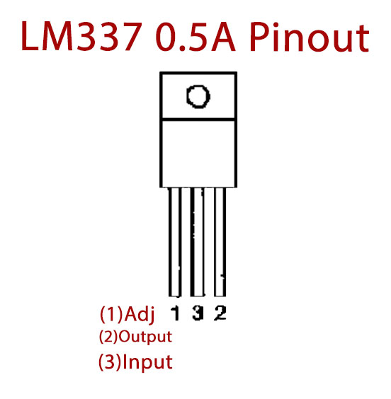
For a detailed description of pinout, dimension features, and specifications download the datasheet of LM337
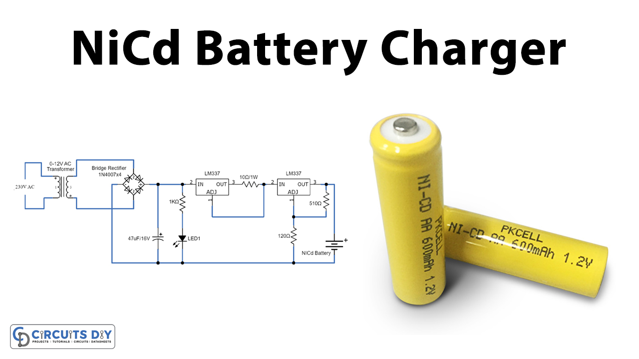
NiCd Battery Charger Circuit
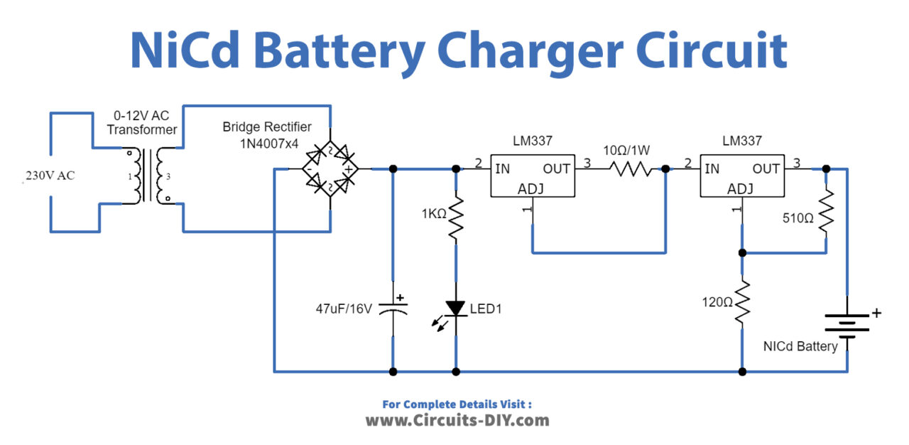
Working Explanation
Here we construct a NiCd Battery charger circuit, we have a power supply section consisting of a 0–12-volt AC step-down transformer, this transformer is used to convert 230V AC supply into a 12V AC supply, a full-wave bridge rectifier comprising D1 through D4, which converts AC supply into DC supply and the smoothing capacitor C1, C1 performs filter process. Current regulation is achieved by the action of R1 and LED. Rectified DC supply and LED1 Indicate the presence of DC power supply. Apply positive supply to the regulator IC1, it provides constant current regulation. Here the Adj terminal of the IC1 is connected to the output terminal followed by the R2 resistor.
Now IC2 Provides a regulated output voltage at the Out terminal, the output voltage depends on the R3 and R4 Resistors value. You can change these resistors’ values depending on your requirement and for the exact calculation value of the resistor, use the IC LM317 datasheet.
Applications
- It is widely used in handheld and compact electronic devices.
- It can be used for charging the individual battery or battery bank.