A 12-volt battery charger circuit is an essential device that is used to recharge a 12-volt lead-acid battery. The lead-acid battery is widely used in many applications such as automobiles, boats, motorcycles, and more. The battery charger circuit is designed to convert AC power to DC power and charge the battery. In this article, we will discuss the working principle and design of a 12-volt battery charger circuit.
Working Principle of 12 Volt Battery Charger Circuit:
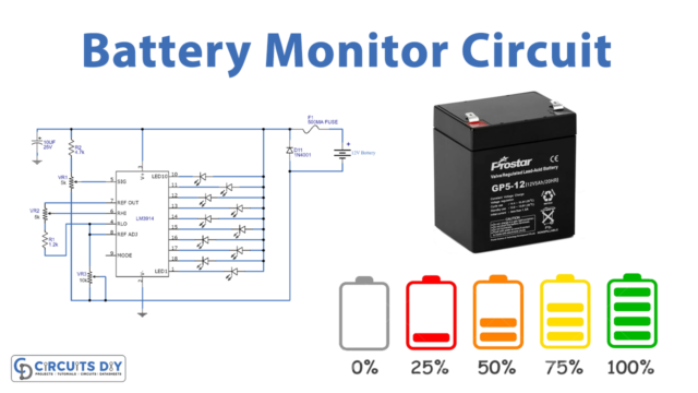
The 12-volt battery charger circuit works on the principle of rectification and voltage regulation. The AC voltage from the mains is first rectified using a bridge rectifier to convert it into DC voltage. The rectified voltage is then filtered using a capacitor to remove any AC ripple. The filtered DC voltage is then fed to a voltage regulator circuit that regulates the voltage to the desired level.
The voltage regulator circuit can be either a linear regulator or a switch-mode regulator. A linear regulator is simple and easy to design, but it is not very efficient. A switch-mode regulator is more complex but is highly efficient and can deliver higher currents.
Design of 12 Volt Battery Charger Circuit:
The design of a 12-volt battery charger circuit can be done using the following steps:
Step 1: Calculate the Charging Current
The first step is to calculate the charging current that is required to charge the battery. The charging current is usually calculated as 10% of the battery capacity. For example, if the battery capacity is 100Ah, then the charging current should be 10A.
Step 2: Choose the Transformer
The second step is to choose the transformer that is required to convert the AC voltage to the desired DC voltage. The transformer should have a voltage rating of at least 12V and a current rating of at least 1.5 times the charging current.
Step 3: Design the Rectifier Circuit
The third step is to design the rectifier circuit. The rectifier circuit can be a bridge rectifier or a full-wave rectifier. A bridge rectifier is preferred as it provides better efficiency and lower ripple.
Step 4: Design the Voltage Regulator Circuit
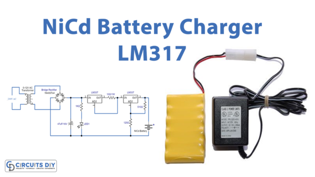
The fourth step is to design the voltage regulator circuit. As mentioned earlier, the voltage regulator circuit can be either a linear regulator or a switch-mode regulator. A linear regulator is simple and easy to design, but it is not very efficient. A switch-mode regulator is more complex but is highly efficient and can deliver higher currents.
Step 5: Choose the Capacitor
The fifth step is to choose the capacitor that is required to filter the DC voltage. The capacitor should have a voltage rating of at least 25V and a capacitance value of at least 1000µF.
Step 6: Design the Current-Limiting Circuit
The sixth step is to design the current-limiting circuit. The current-limiting circuit is required to limit the charging current to the desired level. The current-limiting circuit can be a series resistor or a current-limiting diode.
Step 7: Assemble the Circuit
The final step is to assemble the circuit. The components should be connected as per the circuit diagram. The circuit should be tested and adjusted as per the requirements.
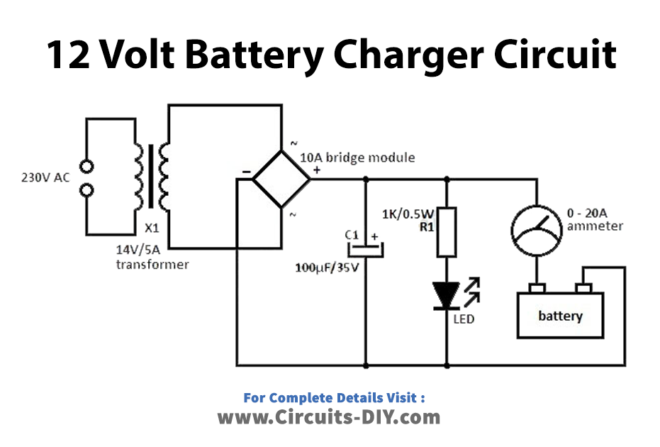
Circuit Diagram
Hardware Components
| S.no | Component | Value | Qty |
|---|---|---|---|
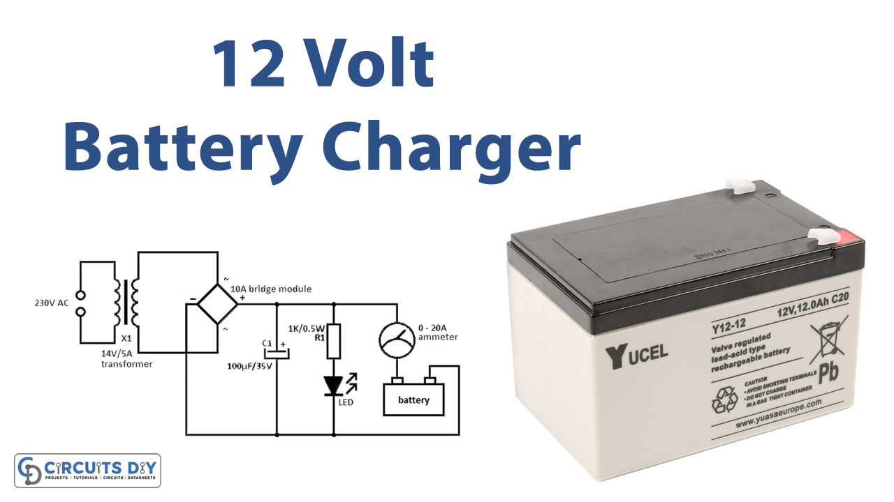
| 1. | Transformer | 14v 5A | 1 |
| 2. | Bridge Rectifier | 10A | 1 |
| 3. | Resistor | 1K 0.5W | 1 |
| 4. | LED | – | 1 |
| 5. | Battery | 12v | 1 |
Conclusion:
A 12-volt battery charger circuit is an essential device that is required to recharge a 12-volt lead-acid battery. The design of the circuit should be done carefully to ensure that the battery is charged safely and efficiently. The circuit should be tested and adjusted as per the requirements.
Applications
- Automotive Industry
- Marine Industry
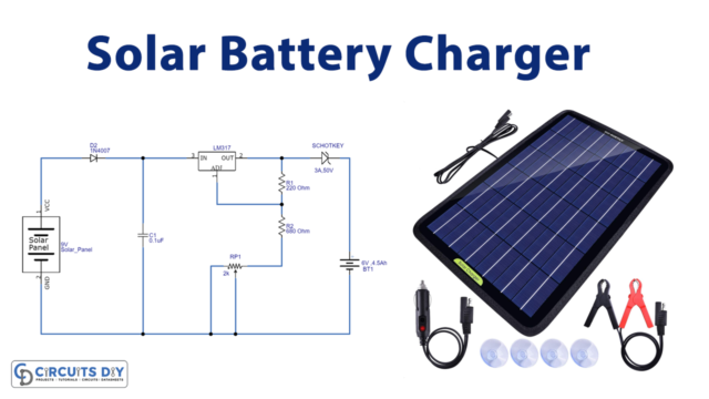
- Solar Energy Systems
- Emergency Backup Power
- Medical Equipment
- Home Automation