You never know when your phones or devices can run out of charging and you’re having an emergency. In these situations, an emergency charger always comes in handy. There are various power banks available in the market but they can be expensive sometimes. This circuit is inexpensive and uses only three components which makes it quite simple to build.
It can be used to charge devices that require 5V input for charging. You can take input of this circuit from any 6,9 or 12V battery. Like you can connect it with your car battery or a 9V PP3 battery for emergency charging.
Hardware Components
The following components are required to make Emergency Cell Phone Circuit
| S.no | Component | Value | Qty |
|---|---|---|---|
| 1. | IC | LM2940CT-5.0 | 1 |
| 2. | DC Supply | 6, 9 or 12V | 1 |
| 3. | Electrolytic Capacitor | 0.33uF, 33uF | 1, 1 |
| 4. | USB port | Type B Female | 1 |
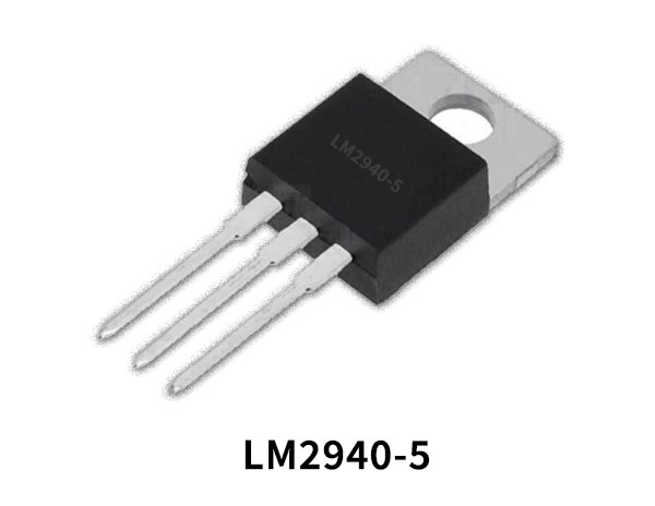
LM2940 Pinout
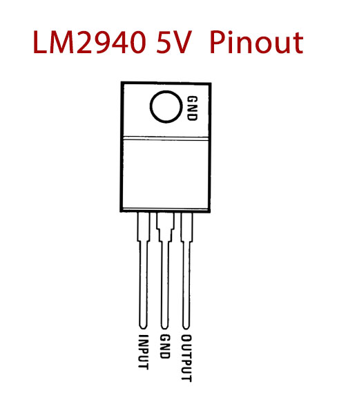
For a detailed description of pinout, dimension features, and specifications download the datasheet of LM2940
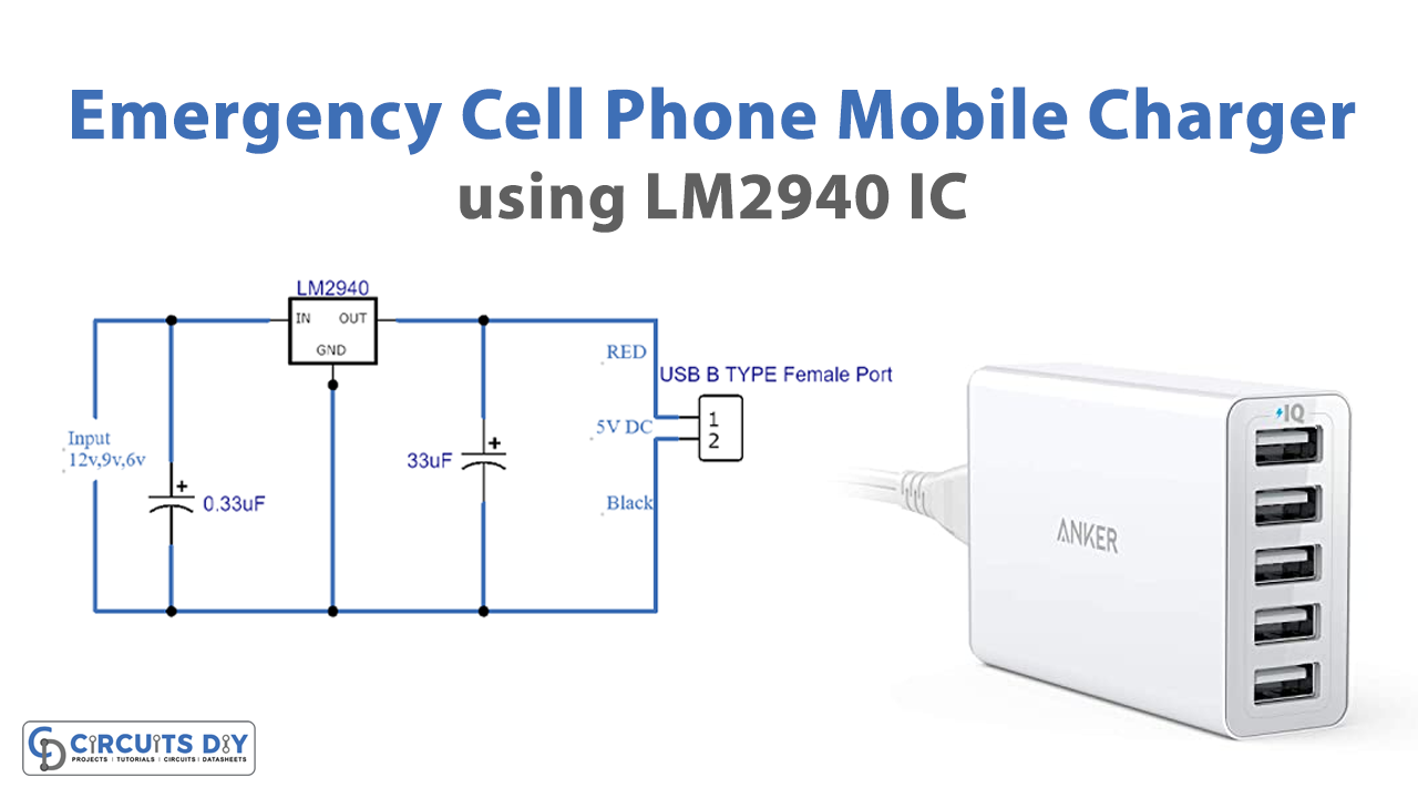
Emergency Cell Phone Circuit
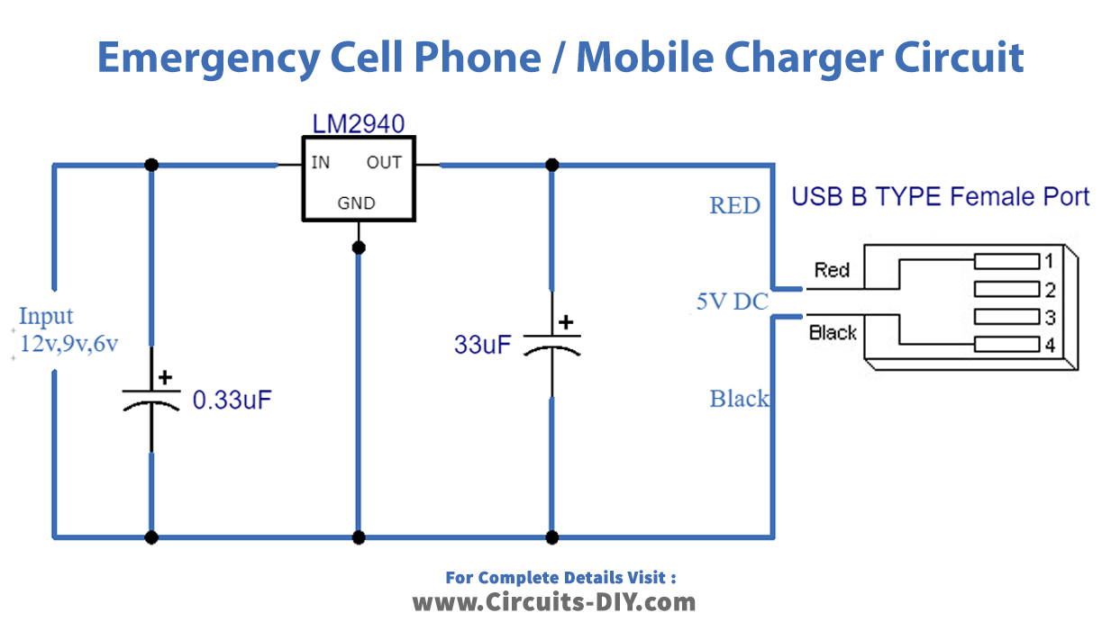
Working Explanation
This circuit can be made easily as it is using just three components. This circuit is working around a voltage regular IC, LM2940CT-5.0. This IC provides an accurate fixed voltage of 5 volts at the output of this circuit. The reason we chose this IC other than LM7805 as it also provides a fixed voltage of 5V is that LM2940CT-5.0 IC is more efficient for emergency charging. It provides 5V with only a 0.5V difference. A 9V PP3 battery will charge the device until it reaches 5.5V or less.
This circuit provides a maximum output current of 1 Ampere which is enough for charging most USB charging devices. This IC has a tendency of becoming warm during operation so you must use a suitable Heatsink with it.
Applications and Uses
This circuit can be used to charge different devices such as Cellphones, iPads, iPods, Media Players, USB Lights, etc.