Introduction
Supercapacitors are becoming increasingly popular due to their high energy storage capacity and long lifetimes. However, charging them can be challenging without the right circuit. If you want to learn how to build a boost charger circuit for supercapacitors, you’ve come to the right place! In this article, we’ll guide you through creating a primary boost converter circuit to transform a 12V car battery voltage to an elevated 16V for charging a bank of supercapacitors.
So, let’s together with us explore the world of supercapacitors and boost charger circuits together!
What are Super Capacitors?
Supercapacitors, or ultracapacitors, are electronic devices that can store extremely large amounts of electrical charge. Unlike batteries, which store and release energy through chemical reactions, supercapacitors use static electric charge. Supercapacitors have plates with a much larger effective area and a smaller distance between them, which works differently from conventional dielectrics. They are cutting-edge energy storage devices that offer high capacitance, power density, and extended cycle times, effectively bridging the gap between electrolytic capacitors and rechargeable batteries.
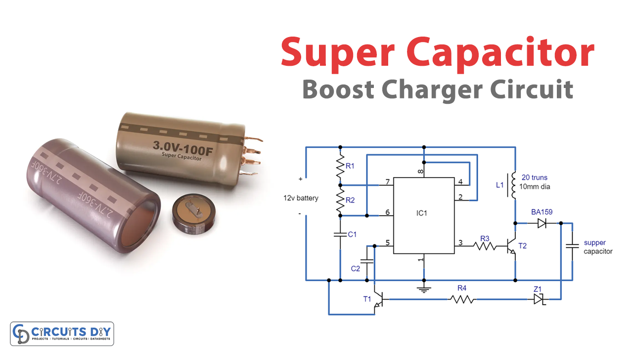
Boost Charger Circuit for Super Capacitors
Hardware Required
| S.no | Components | Value | Qty |
|---|---|---|---|
| 1 | IC | LM555 | 1 |
| 2 | Capacitor | C1= 680pF, C2=0.01uF | 1 1 |
| 3 | Resistor | R. R4 = 100K R2 = 39K, R3 = 100 Ohms, | 2 1 1 |
| 4 | Transistor | T1= TIP122 | 2 |
| 5 | Inductor | L1 = 20 Turns 25 SWG on 10 mm dia ferrite rod | 1 |
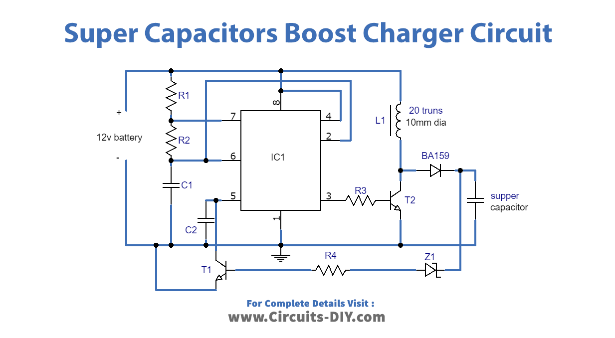
Circuit Digram
Circuit Explanation
The boost charger circuit for charging supercapacitor banks consists of an IC 555 set up as a high-frequency astable. High frequency is required to generate a compact ferrite coil that generates the required stimulated voltage. The IC’s relatively low current output is heightened using T1, which switches the linked ferrite inductor at the frequency of the stable.
IC 555 as a High-Frequency Astable
The IC 555, as a high-frequency stable, generates the necessary signal for charging the supercapacitors. The frequency is set to be high enough to generate a compact ferrite coil, which becomes responsible for generating the required stimulated voltage. The IC 555 generates a relatively low current output amplified using T1, which switches the ferrite inductor at the rate of the astable frequency.
Inductor T1 and BA159 Quick Recovery Diode
The inductor T1 and the BA159 quick recovery diode play a crucial role in the operation of the boost charger circuit. The low current output from the IC 555 is amplified using T1, which switches the connected ferrite inductor. The inductor generates a boosted voltage across it that is effectively increased using the BA159 quick recovery diode. The cathode of the diode is then provided to the connected supercapacitors for charging the devices.
Charging the Super Capacitors
The boosted voltage generated across the diode charges the connected supercapacitors. A loop from the output to the base of T2 maintains a constant voltage for the supercapacitors. If the voltage rises above the fixed value, the feedback loop triggers Z1, which switches ON T2, grounding pin5 of the IC and reducing the pulse width of the pin3 frequency. This process immediately reduces the output to safe limits, and the cycle continues to switch, ensuring the voltage remains within the predetermined thresholds.
Feedback Loop for Voltage Regulation
The feedback loop is a critical aspect of the circuit that ensures the voltage across the supercapacitors remains constant. The feedback loop monitors the output voltage and triggers Z1, which switches ON T2 if it exceeds the fixed value. The T2 grounds pin5 of the IC, which reduces the pulse width of the pin3 frequency. Ensuring that the output remains within safe limits.
Final Words
In conclusion, the boost charger circuit for supercapacitors is an efficient way to charge supercapacitors by converting a 12V car battery voltage to an elevated 16V. We hope our tutorial will help you make and understand this project. Try out this circuit, and for any query, leave a question in the comment section. We would love to help and respond to you.