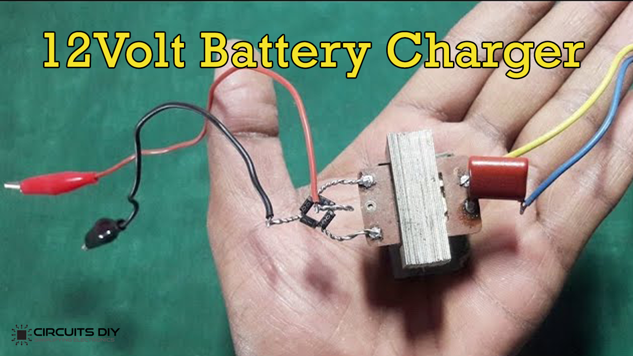
What is a Battery Charger?
A Battery charger is a simple electronic device that is used to force energy into a secondary cell or battery by pushing an electrical current through it. They are relatively inexpensive & easy to build at home. So, in this article, we are going to go over a step-by-step instructions on How to Make A 12V Battery Charger. So let’s get into it.
They are many variations of battery chargers available in today’s market such as Pulse chargers, Trickle Chargers & fast chargers, etc. But generally, all chargers follow the same schematic scheme. A Step-down transformer along with an X-rated Capacitor connected in series to lower the high input AC to a usable level & a bridge rectifier to convert the AC signal into a rippling DC. You can also use a smoothing capacitor to the output of the rectifier to get rid of any noise.
Hardware Components
The following components are required to make 12V Battery Charger Circuit
| S.No | Component | Value | Qty |
|---|---|---|---|
| 1) | Step-Down Transformer | 220V/14V/1.43A/50Hz | 1 |
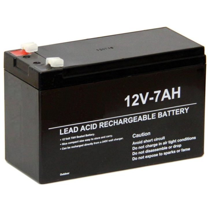
| 2) | Lead Acid Battery | 12V/7Ah | 1 |
| 3) | Diode | 1N4007 | 4 |
| 4) | AVO Meter w/ probes | – | 1 |
| 5) | Film Capacitor | 1uF/105j/440V | 1 |
| 6) | Alligator clips | – | 1 |
| 7) | Soldering Iron | 45W – 60W | 1 |
| 8) | Soldering wire & flux | – | 1 |
| 9) | DC Power Jack | – | 1 |
| 10) | AC Power Plug | 2-Pin | 1 |
12V Battery Charger Circuit
Useful Steps
Follow the steps on how to make a 12V Battery charger
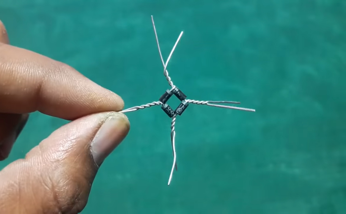
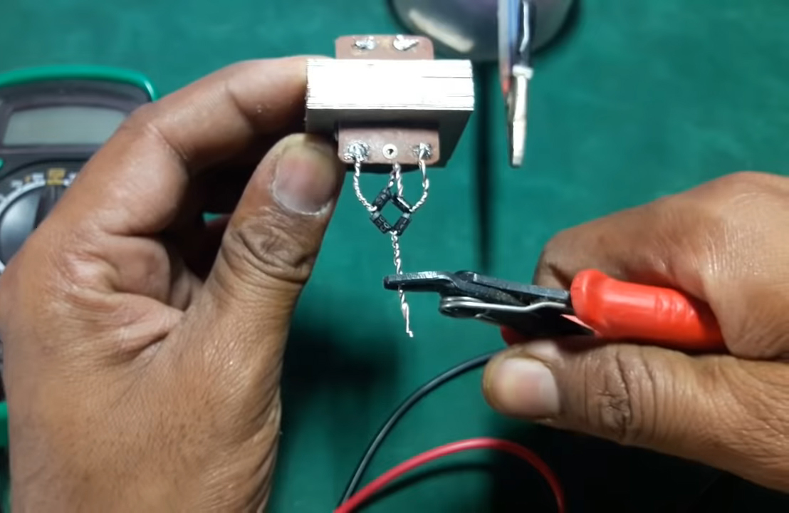
1) Make a Bridge rectifier by connecting 4 1N4007 Diodes in the following configuration.
2) Solder the +ve & -ve Terminals of the bridge rectifier to the secondary winding of the Non-C.T Transformer
3) Trim excess leads of the bridge rectifier.
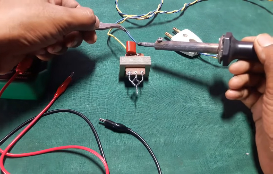
4) Solder one end of the X-rated capacitor to the +ve terminal of the AC supply & other to the primary of the transformer. Solder the -ve terminal of the supply to the primary of the transformer.
5) Solder alligator clips to the terminals of the bridge rectifier.
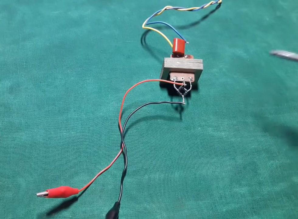
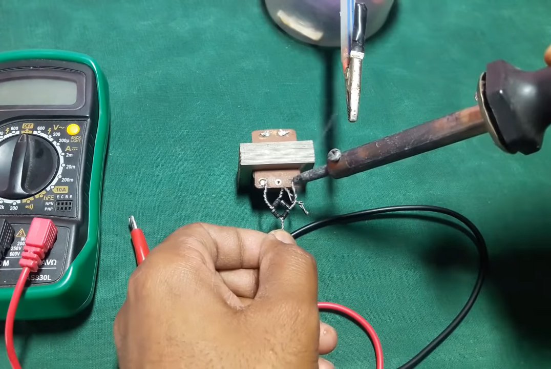
6) Connect the output terminals of the charger to the terminals of the DC power jack & test the circuit.
Battery Charging (Fuse Engaged)
Battery Not Charging (Fuse Disengaged)
Working Explanation
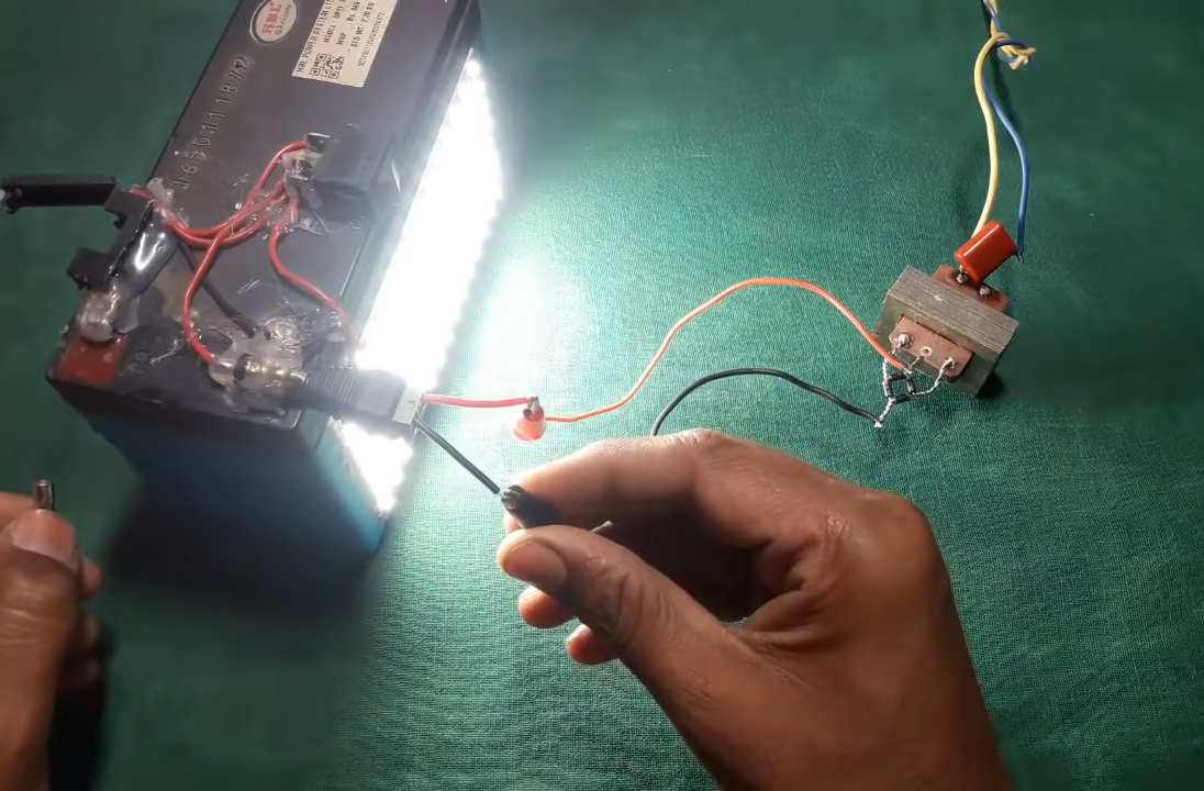
The working of this circuit is pretty simple. A 220V AC signal acts as the input for the charger circuit. this AC signal goes through a 1uF X-rated capacitor directly connected to the live AC line in order to drop the AC Voltage. The Output signal goes through a non-C.T stepdown transformer.
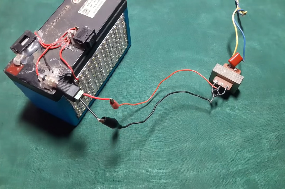
The output AC signal is then fed to a bridge rectifier circuit made by using four 1N4007 diodes. The DC output from the bridge rectifier is then used to charge any 12V lead-acid battery using battery clips.
Applications
- It is commonly used to charge 12V Lead Acid Batteries for emergency backup power.
1 thought on “How to Make A 12V Battery Charger At Home – DIY”
Comments are closed.