Introduction
No one may be unaware of the chargers. We use it every day. Every one of us has that device. We can not deny that our lives depend on gadgets these days and the life of these gadgets depends on their chargers. However, the battery charger we are going to discuss is not for those gadgets we use in our daily lives every day but we use it in deep cycle applications. So, in this tutorial, we are going to the “12 Volt Gel cell Battery Charger Circuit”. Let us discuss a little about the gel cell battery.
We know gel batteries as gel batteries because they use silica to change the acid inside the battery into a thick liquid. We consider these batteries the same as the AGM Batteries. Both of the batteries provide a deep cycle and are flexible to use.
Hardware Required
| S.no | Component | Value | Qty |
|---|---|---|---|
| 1. | NPN Transistor | 2N2222A | 1 |
| 2. | Voltage Regulator IC | LM317 | 1 |
| 3. | Potentiometer | 10KΩ | 1 |
| 5. | LED | – | 1 |
| 7. | Capacitor | 0.1µF | 2 |
| 8. | Resistor | 1KΩ, 2.2KΩ, 470Ω, 1Ω/2W | 1, 1, 1, 1 |
| 9. | DC Supply | 15V-18V | 2 |
Circuit Diagram
Working Explanation
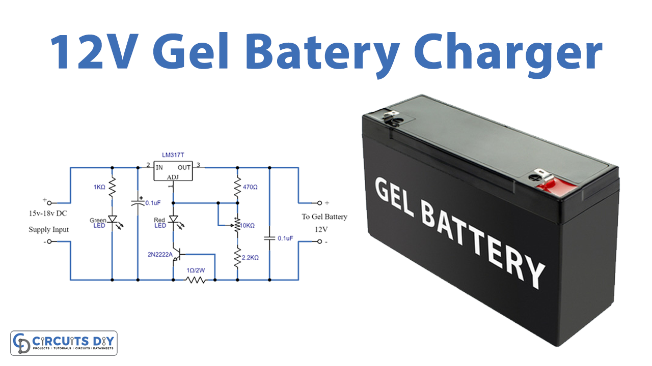
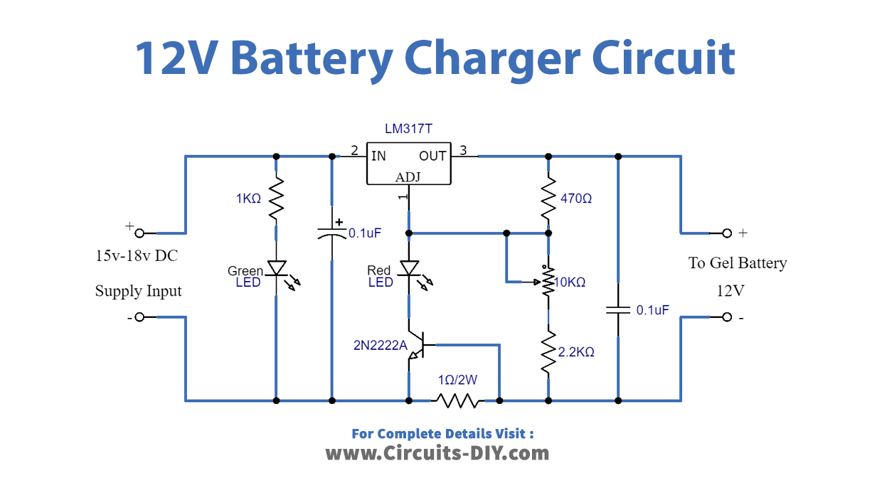
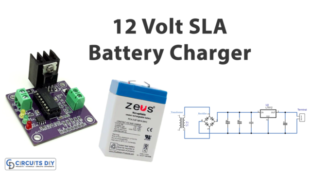
We intend to make this 12 Volt Gel cell Battery Charger circuit to meet the obligations of Gel cell batteries and we made this circuit for charging 12 Volt battery. A primal part of this circuit is the Positive Adjustable Voltage Regulator IC LM317. Make sure to use the heat sink for this. Place Transistor 2N2222A between the Adj pin of the Regulator and ground supply. The Resistor R2 isolates the base terminal and emitter. Resistors R3, potentiometer Rv1, and resistor R4 are associated sequentially between output bias. The LED in the circuit shows the charging current.
Application and Uses
- To charge the battery for deep cycle applications.
Thank you!