The single-cell Li-ion battery charger has many current cutoff points, which permits its operation from either a USB port or a higher power input supply. For example, an AC adapter and wireless charging are some of these types of devices. For an adaptable system, the battery charges in three different stages:
- Precharge
- Quick charge steady current
- And constant voltage
Moreover, the LTC1731 is a constant current and constant voltage linear charger. It is utilized for some single-cell lithium-ion batteries. Moreover, Nickel-cadmium (NiCd) and nickel-metal-hydride (NiMH) batteries can likewise charge with constant current by utilizing their outer terminal points.
Hence, the Li-ion battery charger is a voltage-limiting device. It is similar to lead-acid systems. The difference between these two batteries is, that Li-ion has a higher voltage for each cell as compared to NiCd batteries. Moreover, it has a good voltage resistance and the nonattendance of trickle or floats charge at full charge mode.
Hardware Components
The following components are required to make 1.5A Li-Ion Battery Charger Circuit
| S.no | Component | Value | Qty |
|---|---|---|---|
| 1. | Battery Charger | LTC1731-4.2 | 1 |
| 2. | Schottky Power Rectifier | MBRM120T3 | 1 |
| 3. | Resistor | 1k, 0.2Ω, 19.6k | 1 |
| 4. | Capacitor | 0.1µF Timer, 1µF, 10µF | 1 |
| 5. | LED | – | 1 |
| 6. | P-Channel MOSFET | Si9430DY | 1 |
| 7. | Li-Ion Battery | Discharged | 1 |
Si9430DY Pinout
1.5A Li-Ion Battery Charger Circuit
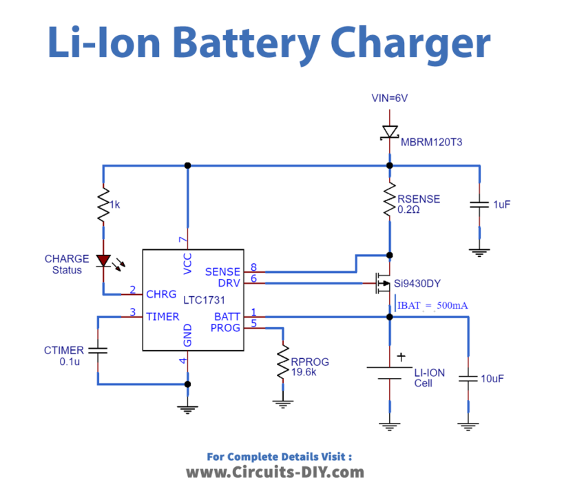
Working Explanation
In this circuit, the outer resistor sets the accuse current of 5%. Also, an internal resistor divider sets the last float potential with 1% exactness. The yield float voltage is set internally to 4.1V. At the point when the input supply is evacuated. The LTC1731 automatically enters a low current rest mode, dropping the battery channel current to ordinarily 7A.
An inside Comparator identifies the end of charge (C/10) condition. While an automatic timer using an outer capacitor sets the charge time. Completely discharged cells are consequently trickle-charged at 10% of the modified current. Until the cell voltage surpasses 2.457V. The LTC1731 is accessible in the 8-pin MSOP packages.
Applications and Uses
- High-Efficiency Switch Mode Charger
- Separate power path control
- Thermal Regulation Protection
- Over and under voltage surge protection