Introduction
Are you tired of constantly replacing batteries for your devices? Why not harness the power of the sun to create your own battery charger? In this article, we will discuss a basic 6V solar battery charger circuit with an automatic cut-off function and overcurrent protection. With the help of a few components, you can make your own charger that can be controlled by a solar panel or an AC/DC adapter.
So, let’s dive into the world of renewable energy and learn how to create a solar battery charger!
Hardware Required
| S no | Components | Value | Qty |
|---|---|---|---|
| 1 | IC | LM317 A1 to A4 = LM324 | 1 1 |
| 2 | Transistor | BC547, TIP122 | 1, 1 |
| 3 | Resistor | 120, 560, 1, 10k, 1k, | 1, 1, 1, 1, 5 |
| 4 | V. Resistor | 1k | 5 |
| 5 | Zener Diode | 3v | 1 |
| 6 | Diode | 1N4007, 5V, 5.5V, 6.5, 7v | 3, 1, 1, 1, 1 |
| 7 | Battery | 6V 4.5aH | 1 |
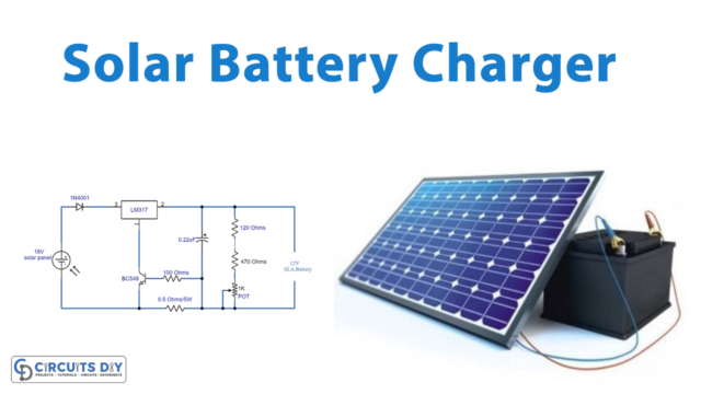
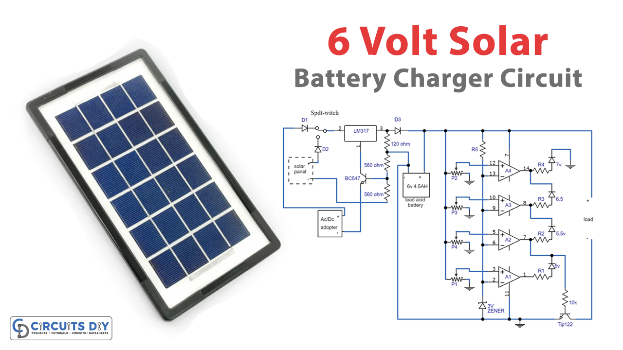
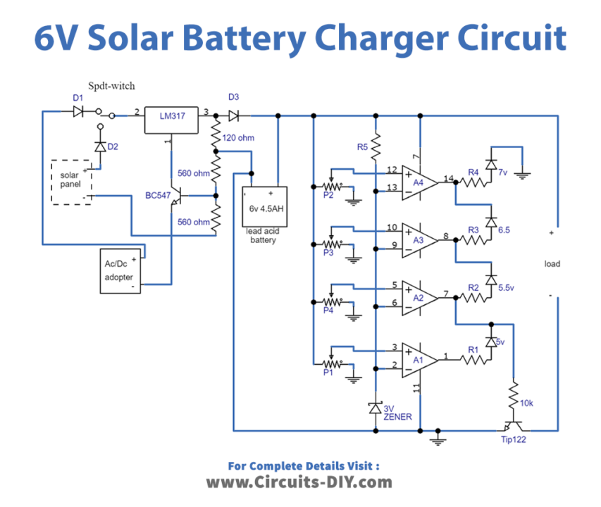
Circuit Diagram
Circuit Explanation
To build the solar battery charger, you must first connect the LM317 voltage regulator IC and the BC547 transistor with the help of resistors and capacitors. Then, connect the LED indicators and the voltage comparators using the LM324 quad op-amp. Finally, connect the battery to be charged to the output of the LM317 IC and select the input from the solar panel or the AC/DC adapter.
Understanding the LM317 Voltage Regulator IC:
The LM317 voltage regulator IC is a common component used to regulate the voltage output of a circuit. In the 6V solar battery charger circuit, the LM317 is set up to generate a fixed 7V output using the resistances 120 ohms and 560 ohms.
Voltage Comparators and LED Indicators: How They Work:
The voltage comparators in the LM324 quad op-amp are used to compare the voltage levels during the charging or discharging process of the battery. The associated LED indicators provide a visual indication of the different voltage levels. The yellow LED connected to A2 is set to show the low voltage cut-off threshold, while the A4 LED indicates the upper full charge level of the battery.
Overcurrent Protection and Low Voltage Cut-Off: Why They Are Important:
The BC547 transistor and its base 1-ohm resistor ensure that the charging current to the 6V/4.5AH battery never exceeds the maximum 500mA mark, thus providing overcurrent protection. The yellow LED indicates the low voltage cut-off threshold, ensuring that the battery is not discharged to harmful unrecoverable limits.
Troubleshooting Common Issues with Your Solar Battery Charger:
Suppose you encounter issues with your solar battery charger, such as the battery not charging or the LED indicators not working. In that case, you can check the connections and make sure the components function correctly. You can also use a voltmeter to measure the voltage output and check if it matches the desired output.
Tips for Maintaining Your Solar Battery Charger:
To maintain your solar battery charger, you should regularly clean the solar panel to ensure maximum efficiency and store the charger in a dry and cool place when not in use. You can also use a battery tester to check the battery’s performance.
Final Words
With the increasing demand for renewable energy sources, creating a solar battery charger is a great way to utilize the power of the sun. In this article, we discussed a primary 6V solar battery charger circuit that you can easily make with the help of a few components. By incorporating an automatic cut-off function and overcurrent protection, you can ensure your battery is charged safely and efficiently. So, give it a try and take a step toward a sustainable future!