Introduction
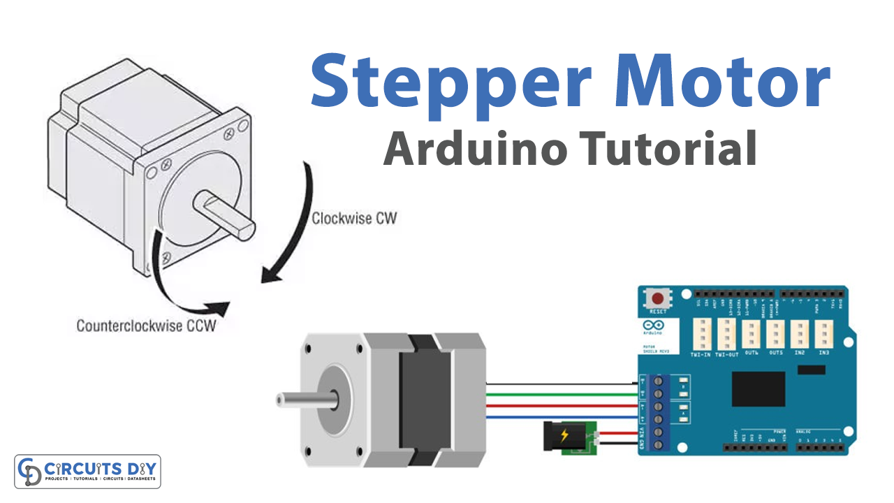
An Arduino UNO-controlled stepper motor using an Arduino Motor shield R3 is a powerful and versatile solution for precise positioning and control of AC/DC stepper motors in a wide range of applications. The Arduino UNO MCU is a powerful and versatile platform that allows for easy control of AC/DC motors through the use of its digital I/O pins and built-in libraries.
Stepper motors are a class of DC/AC motors that can be controlled to rotate in precise steps, making them ideal for applications that require precise positioning and control. An Arduino Motor Shield R3 is an expansion board for the Arduino microcontroller platform that provides an easy way to interface with and control various motors, including DC motors and stepper motors. The shield contains two H-bridge motor drivers, which can drive two DC motors or one stepper motor.
Hardware Components
You will require the following hardware for Interfacing Stepper Motor with Arduino.
| S.no | Component | Value | Qty |
|---|---|---|---|
| 1. | Arduino UNO | – | 1 |
| 2. | USB Cable Type A to B | – | 1 |
| 3. | Arduino Motor Shield R3 | – | 1 |
| 4. | Stepper Motor | – | 1 |
| 5. | Power Adapter for Arduino | 9V | 1 |
| 6. | Jumper Wires | – | 1 |
Stepper Motor with Arduino
- Include the Stepper.h library:
#include <Stepper.h>
- Define the number of steps per revolution for the stepper motor:
const int stepsPerRevolution = 200;
- Give names to the motor control pins:
#define pwmA 3
#define pwmB 11
#define brakeA 9
#define brakeB 8
#define dirA 12
#define dirB 13
- Initialize the Stepper library on the motor shield with the number of steps per revolution and the direction pins:
Stepper myStepper = Stepper(stepsPerRevolution, dirA, dirB);
- In the setup() function, set the PWM and brake pins so that the direction pins can be used to control the motor. Then, set the PWM pins to high and the brake pins to low to enable the motor:
pinMode(pwmA, OUTPUT);
pinMode(pwmB, OUTPUT);
pinMode(brakeA, OUTPUT);
pinMode(brakeB, OUTPUT);

digitalWrite(pwmA, HIGH);
digitalWrite(pwmB, HIGH);
digitalWrite(brakeA, LOW);
digitalWrite(brakeB, LOW);
- Set the speed of the motor in RPMs:
scssCopy codemyStepper.setSpeed(60);
- In the loop() function, step the motor one revolution in one direction, wait for 2 seconds, then step one revolution in the other direction and wait for another 2 seconds:
myStepper.step(200);
delay(2000);
myStepper.step(-200);
delay(2000);
Schematic
Make connections according to the circuit diagram given below.
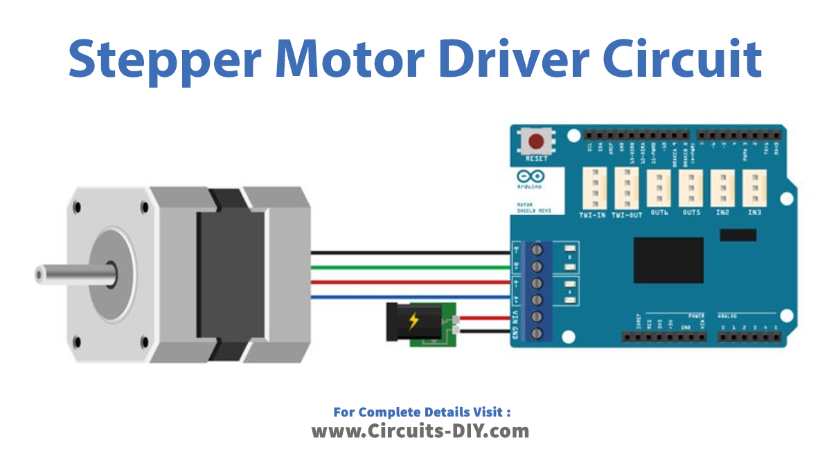
Wiring / Connections
| Servo Motor | Arduino Motor Shield |
|---|---|
| – | +12v External |
| GND | GND External |
| A+ | Channel A+ |
| A- | Channel A- |
| B+ | Channel B+ |
| B- | Channel B- |
Installing Arduino IDE
First, you need to install Arduino IDE Software from its official website Arduino. Here is a simple step-by-step guide on “How to install Arduino IDE“.
Installing Libraries
Before you start uploading a code, download and unzip the following libraries at /Progam Files(x86)/Arduino/Libraries (default), in order to use the sensor with the Arduino board. Here is a simple step-by-step guide on “How to Add Libraries in Arduino IDE“.
Code
Now copy the following code and upload it to Arduino IDE Software.
// Include the Stepper library:
#include <Stepper.h>

// Define number of steps per revolution:
const int stepsPerRevolution = 200;

// Give the motor control pins names:
#define pwmA 3
#define pwmB 11
#define brakeA 9
#define brakeB 8
#define dirA 12
#define dirB 13

// Initialize the stepper library on the motor shield:
Stepper myStepper = Stepper(stepsPerRevolution, dirA, dirB);

void setup() {
  // Set the PWM and brake pins so that the direction pins can be used to control the motor:
  pinMode(pwmA, OUTPUT);
  pinMode(pwmB, OUTPUT);
  pinMode(brakeA, OUTPUT);
  pinMode(brakeB, OUTPUT);

  digitalWrite(pwmA, HIGH);
  digitalWrite(pwmB, HIGH);
  digitalWrite(brakeA, LOW);
  digitalWrite(brakeB, LOW);

  // Set the motor speed (RPMs):
  myStepper.setSpeed(60);
}


void loop() {
  // Step one revolution in one direction:
  myStepper.step(200);

  delay(2000);

  //Step on revolution in the other direction:
  myStepper.step(-200);

  delay(2000);
}he motor speed (RPMs):
  myStepper.setSpeed(60);
}

void loop() {
  // Step one revolution in one direction:
  myStepper.step(200);

  delay(2000);

  //Step on revolution in the other direction:
  myStepper.step(-200);

  delay(2000);
}
Working Explanation
In the setup function, the PWM and brake pins are set to output mode and then set to the appropriate values to allow the direction pins to control the motor. The motor speed is also set to 60 RPMs using the setSpeed function of the Stepper library.
In the loop function, the motor is commanded to step one revolution in one direction using the step function of the Stepper library, followed by a delay of 2 seconds. Then, the motor is commanded to step one revolution in the other direction, followed by another delay of 2 seconds. This pattern repeats indefinitely.
Applications
- Automation
- Medical equipment
- Industrial control
- Measuring instruments
- Camera and telescope positioning
Conclusion.
We hope you have found this Stepper Motor Circuit very useful. If you feel any difficulty in making it feel free to ask anything in the comment section.
Related posts:
 Soil Moisture Sensor With LCD Display
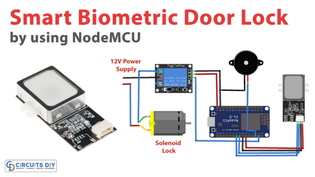 Smart Biometric Door Lock using NodeMCU and Fingerprint Sensor
 Weather Station using RYB080I Bluetooth Low Energy (BLE) Module with Arduino
 Interface nRF24L01 – 2.4GHz RF Transceiver Module With Arduino UNO
 Controlling DC, Stepper & Servo with L293D Motor Driver
 WS2812B Addressable RGB LED Interfacing with Arduino