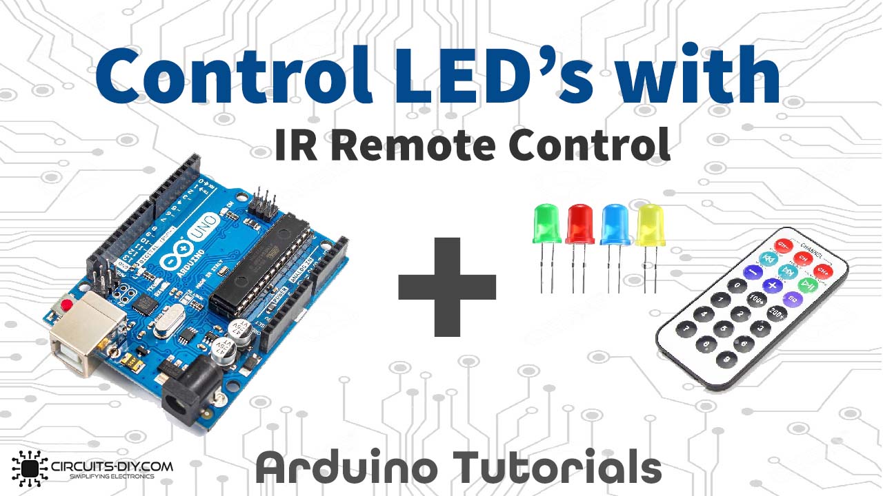
Introduction
An infrared receiver is a component that delivers the data from the remote control to another device. First, it receives the signal then decodes that signal. In electronic, it is used in short-range communication. For example, optical fibers, remote controls, security systems uses have these IR receivers. But, in this article, we are exclusively discussing IR remote control and Arduino UNO interfacing with LEDs. In short, this blog is about controlling the LEDs using IR remote control and Arduino UNO code.
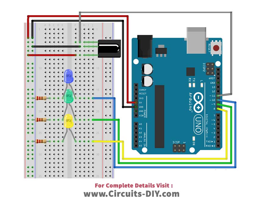
In this tutorial, we are going to interface “LEDs with IR Remote Control with Arduino UNO”. But, before creating the circuit, we first need to learn the pin configuration of the IR receiver. The infrared receiver has just three pins. The first pin is Vout for the output voltage. The second pin is for the ground. And, the third pin is Vcc, which is for the supply voltage.
Hardware Required
| S.no | Component | Value | Qty |
|---|---|---|---|
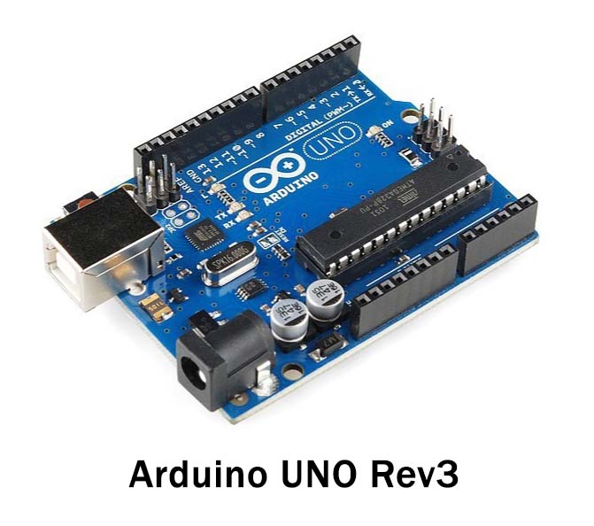
| 1. | Arduino | UNO | 1 |
| 2. | USB Cable Type A to B | – | 1 |
| 3. | Jumper Wires | – | 1 |
| 4. | IR Remote | – | 1 |
| 5. | LED | – | 3 |
| 6. | Resistor | – | 3 |
Circuit Diagram
Connection Table
| Arduino | IR RECEIVER |
|---|---|
| D11 | OUT |
| GND | GND |
| 5V | VCC |
Arduino Code
// Circuits DIY // For Complete Details Visit -> https://circuits-diy.com #includeint IR_Recv = 11; //IR Receiver Pin 3 int bluePin = 10; int greenPin = 9; int yellowPin = 8; IRrecv irrecv(IR_Recv); decode_results results; void setup(){ Serial.begin(9600); //starts serial communication irrecv.enableIRIn(); // Starts the receiver pinMode(bluePin, OUTPUT); // sets the digital pin as output pinMode(greenPin, OUTPUT); // sets the digital pin as output pinMode(yellowPin, OUTPUT); // sets the digital pin as output } void loop(){ //decodes the infrared input if (irrecv.decode(&results)){ long int decCode = results.value; Serial.println(results.value); //switch case to use the selected remote control button switch (results.value){ case 551520375: //when you press the 1 button digitalWrite(bluePin, HIGH); break; case 551495895: //when you press the 4 button digitalWrite(bluePin, LOW); break; case 551504055: //when you press the 2 button digitalWrite(greenPin, HIGH); break; case 551528535: //when you press the 5 button digitalWrite(greenPin, LOW); break; case 551536695: //when you press the 3 button digitalWrite(yellowPin, HIGH); break; case 551512215: //when you press the 6 button digitalWrite(yellowPin, LOW); break; } irrecv.resume(); // Receives the next value from the button you press } delay(10); }
Working Explanation
Connect the circuit according to the diagram and insert the above code in an Arduino Uno. After that when you press the IR remote, it will send modulated signals. These signals have data received by the IR. Each button of the remote has some specific data that will be decoded to control the LEDs. And, that’s how the circuit works.
Code Explanation
To control the LEDs, first, you need to install the IR remote library. Define the receiver pin that receives the signal. Here we are using pin 11 for this purpose. Define the pins through which LEDs are connected. Since we are using three LEDs, therefore we have defined three pins for that motive. Yellow, green, and blues pins are connected with pins 8, 9, and 10 of an Arduino. respectively. Now define those pins as output. Define the cases in a void loop to get the output pressing buttons according to your preference.
Application and Uses
With some modification, it can be used to control various other appliances. For example, it can be used for home appliances. And, therefore, it may be used in home automation, office automation, and in other industries