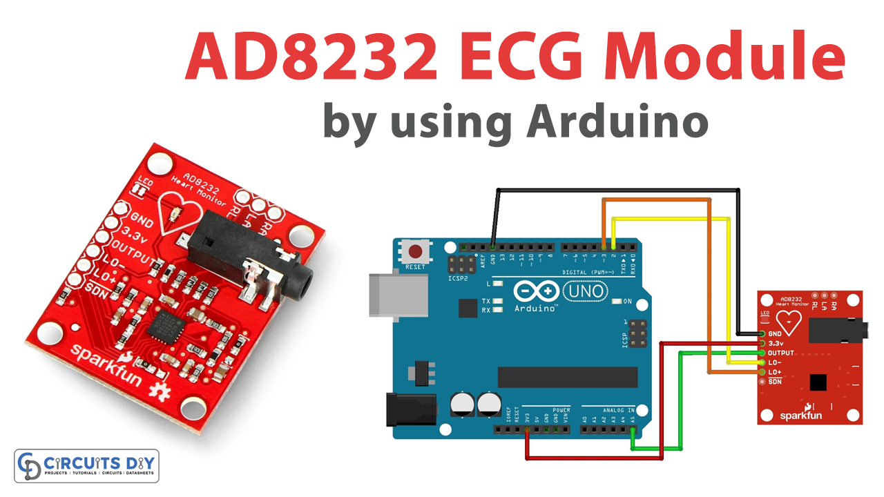
Introduction
The number of heat-related illnesses and the people who suffer from them is rising daily, thus engineers and designers are also doing their part to assist the patients. You may be familiar with the biomedical equipment used to monitor or diagnose a patient’s health. Therefore, even little gadgets can have a big impact on protecting human health. One of those little sensors or monitors, the heart rate monitor, will be covered in this tutorial. So, by reading this article you’ll be able to interface “AD8232 ECG Module with Arduino – Heart Rate Monitor”.
AD8232 ECG Module
By acquiring an electrocardiogram, or ECG, the AD8232 module enables the recording of the electrical activity of the heart. Because electrical signals are transferred through certain routes in the heart and result in the heartbeat, ECG sensors pick up signals from heartbeats. Electrodes applied to the skin, more especially on the arms, legs, and front of the chest can be used to record this electrical activity.
Hardware Overview
Analog devices AD8232 IC, a single-chip designed to collect, amplify, and filter biopotential signals for biopotential measuring applications, is coupled with the AD8232 ECG Module. Since ECG signals may be quite noisy, the AD8232 sensor module includes signal amplifiers and noise filters that have been specifically tuned for ECG signals. The module blocks out the 60Hz noise that is produced by standard home power. Since the module’s output is of the analog variety, soldering the header pins is required to connect it to a microcontroller with analog input pins, such as an Arduino.
Pin Configuration
| Pin Name | Description |
|---|---|
| GND | Ground pin |
| 3.3v | Power Supply pin |
| Output | The output of an operational amplifier. At this output, the heart rate signal has been thoroughly conditioned. An ADC’s input can be linked to OUT. |
| LO- | Output from the Leads Off Comparator. When the electrode to IN is disconnected in the dc leads-off detecting mode, LO is high; when connected, it is low. |
| LO+ | Output from the Leads Off Comparator. When the +IN electrode is disconnected in the dc leads-off detection mode, LOD+ is high; when it is connected, it is low. |
| SDN | Control input for the shutdown. To engage the low power shutdown mode, drive SDN low. |
| RA | Electrode pad RED Biomedical RA (input). Negative Input on an Instrument Amplifier. In most cases, IN is wired to the electrode on the right arm (RA). |
| LA | Biomedical electrode pad in yellow LA (input). Positive Input on an Instrument Amplifier. Normally, +IN is attached to the electrode on the left arm (LA). |
| RL | GREEN Pad for biomedical electrodes RL (input). The output of the right leg drive. Connect the driven electrode to the RLD pin (usually the right leg). |
| 3.5mm ECG Biomedical Electrode Connector Jack | To Combine Biomedical Electrode pad Connector of RA, LA, RL |
Hardware Required
Circuit Diagram
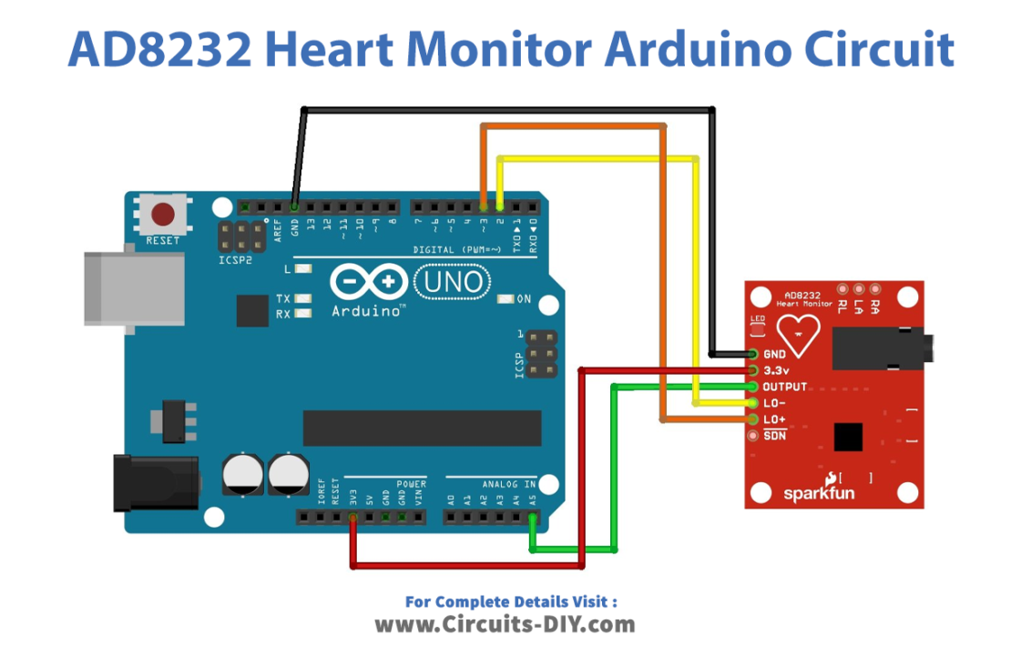
Connection Table
| Arduino UNO | AD8232 Heart Monitor |
|---|---|
| 3.3V | 3.3v |
| GND | GND |
| A5 | OUTPUT |
| D2 | LO- |
| D3 | LO+ |
Arduino Code
void setup() {
  // initialize the serial communication:
  Serial.begin(9600);
  pinMode(3, INPUT); // Setup for leads off detection LO +
  pinMode(2, INPUT); // Setup for leads off detection LO -

}

void loop() {

  if((digitalRead(10) == 1)||(digitalRead(11) == 1)){
    Serial.println('!');
  }
  else{
    // send the value of analog input 0:
      Serial.println(analogRead(A5));
  }
  //Wait for a bit to keep serial data from saturating
  delay(1);
}
Working Explanation
To interface the AD8232 ECG Module with Arduino, make connections according to the given table/Circuit diagram. Use the Arduino IDE to upload this code. Go to tools>Serial Plotter in the Arduino IDE and set the baud rate to 9600. . You may view the results in the form of a graph on the Arduino IDE plotter after the code has been uploaded. Arduino serial plotter will display an output similar to this:

Code Explanation
- The code requires no library so the program starts with the setup. So, in the void setup, we first initialize the serial monitor by Serial.begin. Then by using the PinMode function we define the input pins.
- In the void loop, we give the condition that if pin 10 or 11 is equal to 1, the serial monitor shows ‘!’, otherwise, the analog pin A0 reads the value coming from the sensor and prints it on the Serial monitor. In the last, the program has some delay in getting the new value.
Application and Uses
- ECG Monitoring device.
- Health monitoring systems
- Fitness heart rate monitors
- Biomedical devices, etc