Introduction
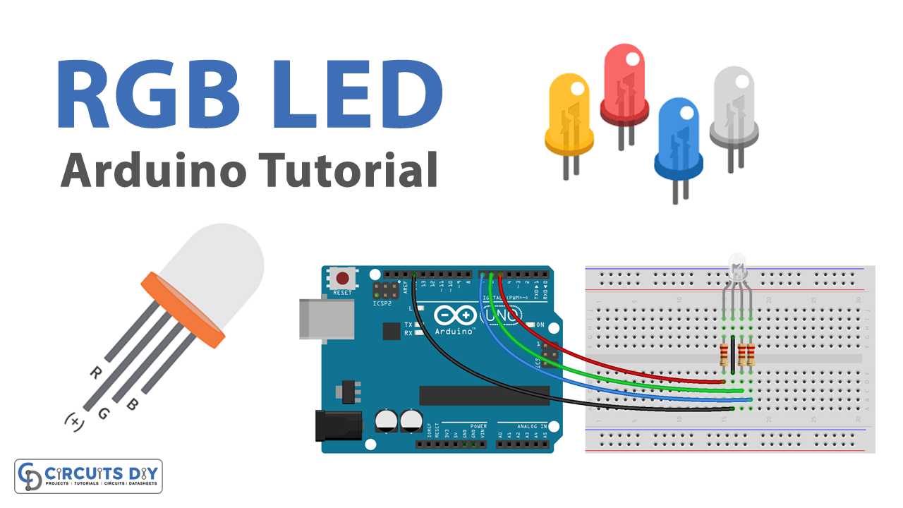
An RGB LED is a light-emitting diode that can produce a range of colors by combining the outputs of red, green, and blue LEDs. Using an Arduino UNO, you can control the intensity of each color and create a variety of color patterns and effects.
Controlling RGB LEDs with an Arduino UNO offers a wide array of applications and usability such as mood lighting, entertainment systems, decorative items, and indicative signaling.
Hardware Components
You will require the following hardware for Interfacing RGB LED with Arduino.
| S.no | Component | Value | Qty |
|---|---|---|---|
| 1. | Arduino UNO | – | 1 |
| 2. | USB Cable Type A to B | – | 1 |
| 3. | 9V Power Adapter for Arduino | – | 1 |
| 4. | RGB LED | – | 1 |
| 5. | Resistor | 220Ω | 3 |
| 6. | Breadboard | – | 1 |
| 7. | Jumper Wires | – | 1 |
Steps Interfacing RGB LED with Arduino UNO
- Connect the RGB LED to the breadboard. Connect the common cathode (short leg) of the LED to a row on the breadboard, and the three long legs to different rows.
- Connect the 220-ohm resistors to the breadboard. Connect one end of each resistor to the same row as the corresponding longer leg of the LED, and the other end to a different row.
- Connect one end of a jumper wire to the row with the common cathode of the LED and the other end to a ground pin on the Arduino board.
- Connect the other end of each resistor to a digital pin on the Arduino board.
- Open the Arduino software on your computer.
- Create a new sketch by clicking on “File” and then “New.”
- Set the pin mode for the digital pins that the LED is connected to by adding the following lines of code at the beginning of the sketch:
pinMode(redPin, OUTPUT);pinMode(greenPin, OUTPUT);pinMode(bluePin, OUTPUT);Replace “redPin,” “greenPin,” and “bluePin” with the actual numbers of the digital pins that the LED is connected to.
- In the loop function, add the following lines of code to turn the LED on and off:
digitalWrite(redPin, HIGH);delay(1000);digitalWrite(redPin, LOW); delay(1000);- To turn on the other legs of the LED, simply repeat the above steps with the appropriate digital pin numbers. For example, to turn on the green leg, use the digitalWrite function with the “greenPin” instead of the “redPin.”
- Upload the sketch to the Arduino board by clicking the “Upload” button in the Arduino software.
Schematic
Make connections according to the circuit diagram given below.
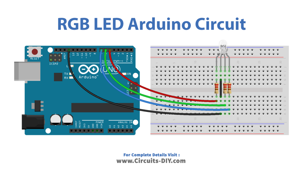
Wiring / Connections
| Arduino | RGB LED (Common Cathode) |
|---|---|
| GND | GND |
| D5 | R |
| D6 | G |
| D7 | B |
Installing Arduino IDE
First, you need to install Arduino IDE Software from its official website Arduino. Here is a simple step-by-step guide on “How to install Arduino IDE“.
Code
Now copy the following code and upload it to Arduino IDE Software.
Arduino – RGB LED Example Code
const int PIN_RED   = 5;
const int PIN_GREEN = 6;
const int PIN_BLUE  = 7;

void setup() {
  pinMode(PIN_RED,   OUTPUT);
  pinMode(PIN_GREEN, OUTPUT);
  pinMode(PIN_BLUE,  OUTPUT);
}

void loop() {
  // color code #00C9CC (R = 0,   G = 201, B = 204)
  analogWrite(PIN_RED,   0);
  analogWrite(PIN_GREEN, 201);
  analogWrite(PIN_BLUE,  204);

  delay(1000); // keep the color 1 second

  // color code #F7788A (R = 247, G = 120, B = 138)
  analogWrite(PIN_RED,   247);
  analogWrite(PIN_GREEN, 120);
  analogWrite(PIN_BLUE,  138);

  delay(1000); // keep the color 1 second

  // color code #34A853 (R = 52,  G = 168, B = 83)
  analogWrite(PIN_RED,   52);
  analogWrite(PIN_GREEN, 168);
  analogWrite(PIN_BLUE,  83);

  delay(1000); // keep the color 1 second
}
When using many colors
const int PIN_RED   = 5;
const int PIN_GREEN = 6;
const int PIN_BLUE  = 7;

void setup() {
  pinMode(PIN_RED,   OUTPUT);
  pinMode(PIN_GREEN, OUTPUT);
  pinMode(PIN_BLUE,  OUTPUT);
}

void loop() {
  // color code #00C9CC (R = 0,   G = 201, B = 204)
  setColor(0, 201, 204);

  delay(1000); // keep the color 1 second

  // color code #F7788A (R = 247, G = 120, B = 138)
  setColor(247, 120, 138);

  delay(1000); // keep the color 1 second

  // color code #34A853 (R = 52,  G = 168, B = 83)
  setColor(52, 168, 83);

  delay(1000); // keep the color 1 second
}

void setColor(int R, int G, int B) {
  analogWrite(PIN_RED,   R);
  analogWrite(PIN_GREEN, G);
  analogWrite(PIN_BLUE,  B);
}
Working Explanation
The working of the source code to control an RGB LED is very simple. To control the LED, the code uses functions such as digitalWrite, delay, and analogWrite. The digitalWrite the function is used to set the digital pin to a high or low state, which turns the RGB LED on or off. The delay function is used to pause the program for a certain number of milliseconds, which allows you to control the duration that the LED is on or off. The analogWrite function is used to control the intensity of the colors by setting a value between 0 and 255, which determines the brightness of the RGB LED.
Applications
- Mood lighting
- Display lighting
- Stage lighting
- Gaming
- DIY projects
Conclusion
We hope you have found this Arduino RGB LED Circuit very useful. If you feel any difficulty in making it feel free to ask anything in the comment section.