Here we’ll teach you how to create a 555 timer IC LED Roulette Circuit and let you know what roulette is before beginning the tutorial, it’s a casino game called after the French word meaning tiny circle.
Similarly, here we render a led blinker in the form of a wheel (or circle) using 555 timer IC in Astable mode and IC 4017 which is a decade counter IC and a limited need. The 4017 IC is a very useful IC for project plays, timer-dependent games, and numerous DOCTRONICS development kits such as Light Chaser and Matrix Die.

Hardware Components
The following components are required to make LED Roulette Circuit
| S.no | Component | Value | Qty |
|---|---|---|---|
| 1. | battery | 9V | 1 |
| 2. | IC | CD4017 | |
| 3. | IC | NE555 Timer | 1,1 |
| 4. | Potentiometer | 10K ohms | 1 |
| 5. | Resistors | 220, 1K | 1 |
| 6. | Capacitors | 10uF | 1 |
| 7. | LEDs | – | 8 |
NE555 IC Pinout

For a detailed description of pinout, dimension features, and specifications download the datasheet of 555 Timer
CD4017 Pinout
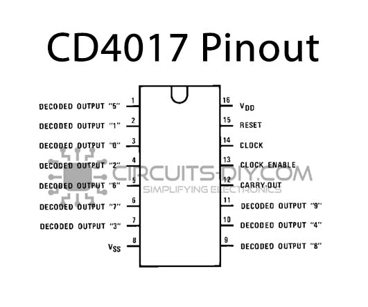
For a detailed description of pinout, dimension features, and specifications download the datasheet of CD4017
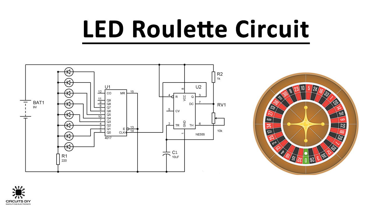
LED Roulette Circuit
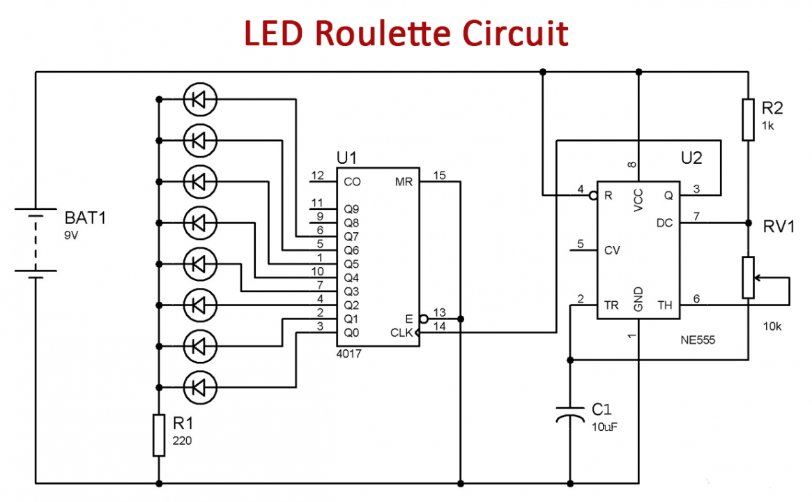
Working Explanation
Now we’re going to blink the LEDs in a roulette configuration (circle shape), as we’ve used 8 LEDs that are linked by the 4017 IC output pins according to output series, start from zero and go up to 10 but we’re just using 8 output pins as the number of LEDs is 8 and it gets the clock pulse orIn Astable mode pulse data from the 555 timer IC.
As the LEDs start blinking we will alter the velocity of the blinking LEDs by adjusting the resistance value via a potentiometer linked in the circuit as increasing the resistance value would shift the oscillation frequency of the 555 timer IC, thus the clock pulse rate.
Application and Uses
- Build ON and OFF sequential of all 10 output PINs required in our LED Roulette circuit.