LEDs are becoming the first choice for automotive exterior lighting. However, the diodes and their drivers need to meet the relevant automotive standards, and additional short circuit and EMI protection may also need to be added. LED drivers are increasingly becoming more integrated to incorporate this protection.
As we know, LEDs are current-driven devices that are substantially affected by changes in operating conditions, such as voltage and temperature. LEDs used in the automotive environment are subject to a wide range of operating conditions, and LEDs can commonly degrade or permanently fail before their expected lifetime. A proper circuit design can enhance LED longevity and performance. So, energy-efficient LED driver circuits should be used in automotive applications for the betterment of batteries. Here LED drivers are devices that regulate and supply the power used to ‘drive’ runs of LED strip lighting. Similar to traditional transformers, they transform mains voltage alternating current to a lower voltage.
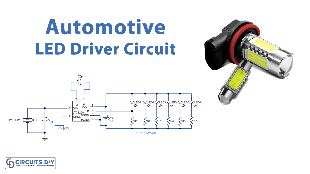
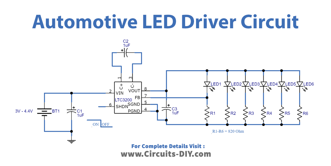
We design an automotive LED driver circuit with DC/DC converter IC LTC3200 from linear technology. This IC is a regulated charge pump that gives up to 100mA output current with low noise constant frequency operation, it takes an input voltage between 2.7V to 4.5V and the circuit with this IC may not require an inductor element.
Hardware Required
| S.no | Component | Value | Qty |
|---|---|---|---|
| 1. | IC | LTC3200 | 1 |
| 2. | Capacitor | 1uF | 3 |
| 3. | Resistor | 82Ω | 6 |
| 4. | LED | – | 6 |
| 5. | Connecting Wires | – | – |
| 6. | Battery | 3V-4.4V | 1 |
Circuit Diagram
LTC3200 Pinout
The LTC3200 comes in an MS8 package and also it is available in a 6-pin ThinSOT package.

Working Explanation
A comprehensive, multi-LED-string driver must support the high voltages and high currents required by high-power LED strings. It must also deftly handle the on/off transitions of some LED strings while others remain on and unaffected. In an automotive environment, it should accommodate wide-ranging input and output voltages, of the battery at the input and the LED strings at its output, and delivery should also have features like low EMI and open and short-circuit fault protection. So, we have used the LTC 3200 automotive LED driver IC, available in 8-Pin MSOP to satisfy these requirements. It is a constant frequency switched capacitor voltage doubler and produces a regulated output voltage from a 2.7V to 4.5V input with up to 100mA of output current. This IC reduces the BOM because it requires only a few external components to operate. We have designed the circuit to work with low voltage and current. If you want to use this circuit in automotive applications then bring the battery voltage and current to 4V by using voltage regulators. Otherwise, you can use an external battery.
As we can see in the circuit 6 White LEDs are connected to the Vout and Pond pins. Here from LED1 feedback signal is given, this acts as an output divider to the feedback pin and it is required to program LTC3200 IC for the output voltage. Now Pins 4 & 5 are tied to the ground supply, and C+ and C- Pins are fed with a flying capacitor, Pin 6 is an active-low shutdown input pin. If low signal approaches to Pin circuit operation will be disabled, for enabling the circuit operation make sure the high or 3V input to this Pin. To control the brightness of LEDs you can also apply a PWM signal to this pin.
Applications
- It can be used in White LED Backlighting.
- This circuit can be used as a headlight or taillight or brightness-controlled lighting application in automobiles.