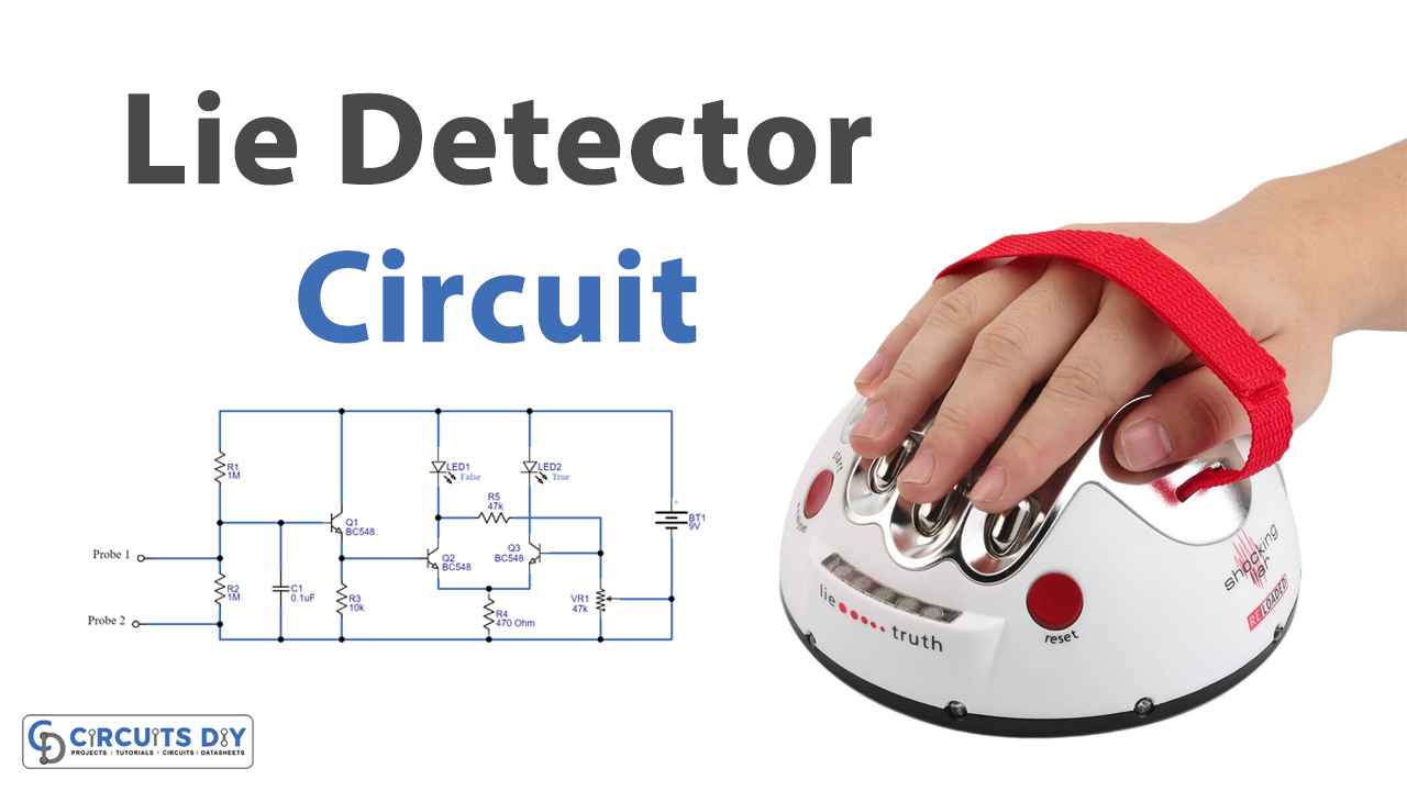
In this tutorial, we are going to make a “Lie Detector Circuit”.
It has been assumed that lying is accompanied by a change in the body’s physiological activity. The instrument used to find whether a person is speaking the truth or not is called a lie detector or polygraph. The polygraph is a set of equipment that accurately measures various sorts of bodily activity such as heart rate, blood pressure, respiration, palmar sweating, body temperature, and tension level of the person undergoing the detector test. In recent years brain activity has also begun to be measured in this setting. When the person tries to speak lies, his body physiology changes.
These changes are recorded and compared with the results that are obtained from normal conditions. Such sophisticated instruments can however give wrong results. Hence the results obtained through the lie detectors are not taken as evidence in court cases. Here we design a simple two transistor-based low-tech version of a real polygraph or lie detector. As we know that emotional stress is not only reflected by heartbeats or trembling hands, but also by an increase in skin moisture. When the skin becomes moist, its resistance decreases. Thus, skin resistance is a good conductor of the stress level of the subject. The simple lie detector circuit presented here has been designed to detect skin resistance, it works based on the skin resistance variations, consider a person who lies during the conversation his anxiety level will rise and it makes him sweat so his hands & finger becomes moisture by using this lie detector circuit, we can detect those moments by the way of conductivity and resistance variation then LEDs glows depends on the moisture & conductivity of the skin.
Hardware Components
The following components are required to make Lie Detector Circuit
| S.no | Component | Value | Qty |
|---|---|---|---|
| 1. | Transistor | BC548 | 3 |
| 2. | LED | – | 2 |
| 3. | Variable Resistor | 47KΩ | 1 |
| 4. | Resistors | 1MΩ, 10KΩ, 47KΩ, 470Ω | 2,1,1,1 |
| 5. | Ceramic capacitor | 0.1μF | 1 |
| 6. | Battery | 9V | 1 |
| 7. | Connecting Wires | – | – |
| 8. | Tiny Copper plate for fingers (you can use copper wire) | – | 1 |
BC548 Pinout
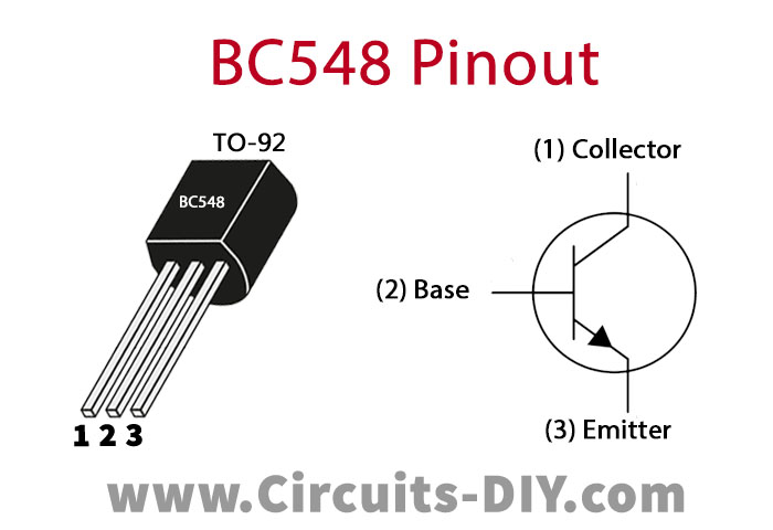
For a detailed description of pinout, dimension features, and specifications download the datasheet of BC548
Lie Detector Circuit
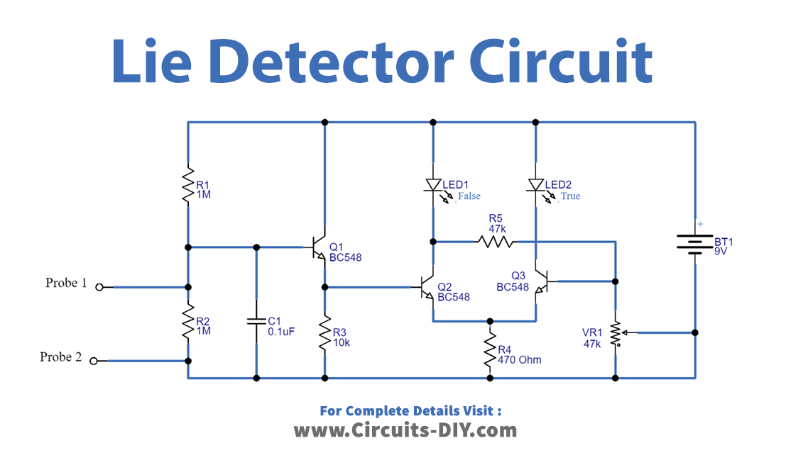
Working Explanation
As we can see in the circuit, the operation of the circuit starts with the R1 and R2 voltage divider circuits. Here the probe checks the resistance of the skin in parallel with R2. So, the voltage drops across R2 depending on the resistance of the skin. If the skin dries (people do not lie), the resistance of about 1M. The voltage is about 4.5V. In another hand, if the skin is moist (liar), the resistance is less than 1M. It makes the voltage less than 4.5V. Here Q1 transistor base terminal takes the input from a finger, it is responsible for detecting the resistance changes in the finger, Red LED connected to the collector terminal of the Q2 transistor this LED represents the detection of a lie. Green LED is connected with Q3 transistor this LED represents the detection of true. Variable resistor VR1 decides the sensitivity level of the circuit. The transistors Q3 and Q1 are connected as a Darlington pair hence the small variation of base voltage Q3 will affect Q1. So based on the resistance of the finger the transistors Q1 and Q3 will decide either to turn on or turn off the LED D2. The LED D2 will turn on only if the transistor Q1 is on, but when this transistor goes on the voltage to the base of The 2 transistor will be low thus keeping the LED D1 turned off. The base voltage of the transistor Q2 can be controlled by the Potentiometer (47K). So, you can use this potentiometer to set the sensitivity of the circuit.
Now when the finger skin resistance is high the Q1 doesn’t get any bias and it becomes turned OFF then Q2 also doesn’t get any bias then Q3 only gets bias through the Q2 collector terminal and the Green LED glows to represent true. If a person lies, the skin conductance increases with the increase of secretion from sweat glands thereby decreasing skin resistance. This circuit determines the low resistance as a lie and high resistance as truth.
Applications
Can be used to find if any person is telling truth or lying.
Thanks for your blog, nice to read. Do not stop.