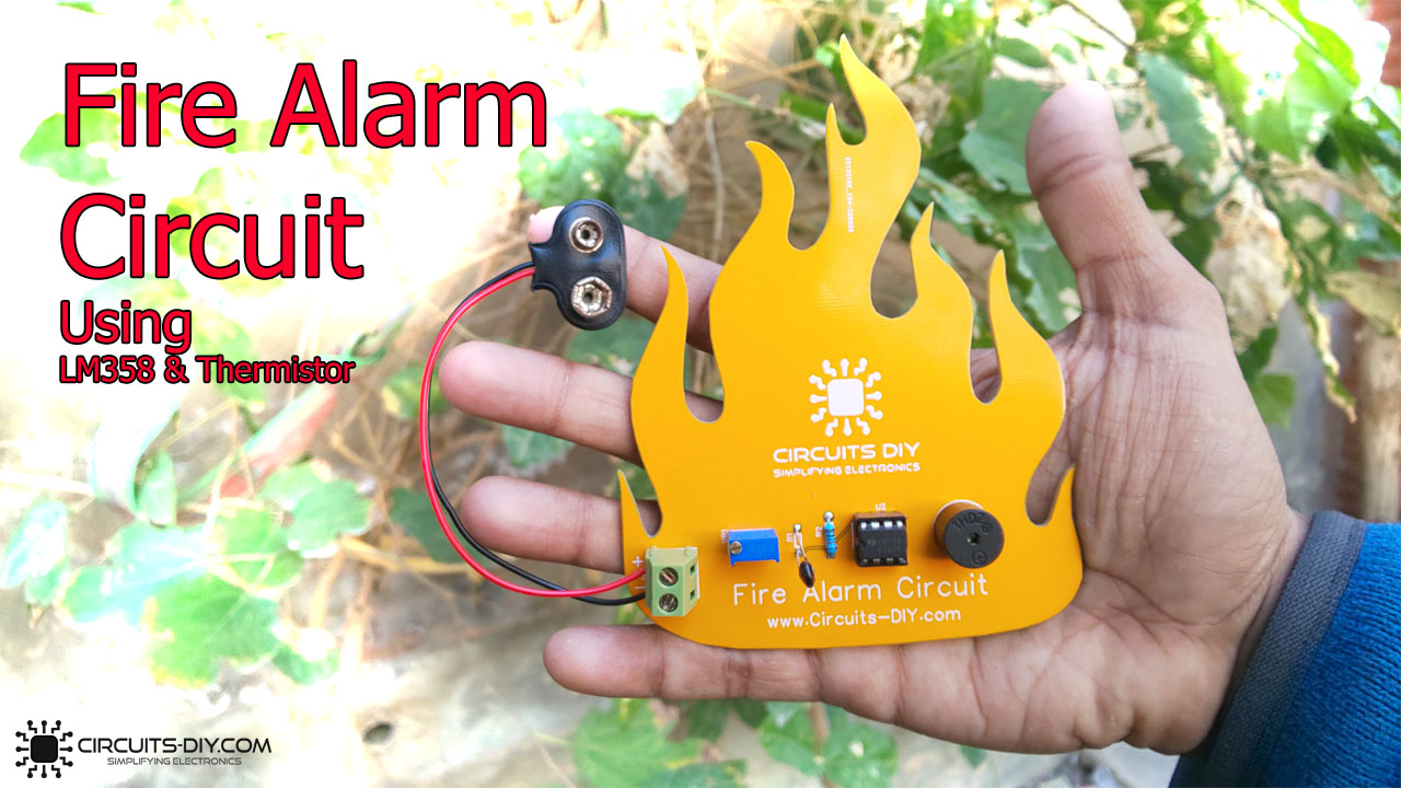
What is a Fire Alarm?
A Fire alarm is a simple electronic circuit that determines the presence of any hazardous fire in its vicinity & triggers an array of preventive measures such as overhead sprinklers or an alarming array. Fire alarms are an integral safety feature in today’s industry, with the government requiring mandatory fire safety SOPs & fire alarm systems for every existing industry. So, in this tutorial, we will go through a step-by-step procedure on how to make a simple fire alarm circuit using a thermistor.
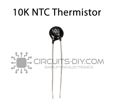
NTC Thermistor
NTC Thermistor is an electronic component that is used to measure temperature. Basically, an NTC thermistor is a type of resistor whose resistance decreases with the increase in temperature. They are made out of a combination of metal oxides which are passed through the sintering process which gives negative electrical resistance versus temperature (R/T) relationship to it. By having a large -ve (R/T) slope, a small change in temperature results in a huge change in the electrical resistance of the thermistor.
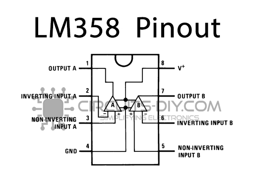
LM358 Op-Amp
An LM358 is a simple operational amplifier that is integrated with two amplifiers that are powered by using a single power supply. The IC offers an outstanding value for cost-sensitive applications, with features including low offset (300 µV, typical), common-mode input range to ground, and high differential input voltage capability. They are commonly used in applications such as integrators, Differentiator, Summer, adder, Voltage followers, Oscilloscopes, etc.

PCBWay commits to meeting the needs of its customers from different industries in terms of quality, delivery, cost-effectiveness, and any other demanding requests. As one of the most experienced PCB manufacturers in China. They pride themselves to be your best business partners as well as good friends in every aspect of your PCB needs.
Hardware Components
You will need the following parts to build this project:
| S.no | Component | Value | Qty |
|---|---|---|---|
| 1. | NTC Thermistor | 10K | 1 |
| 2. | Op-Amp IC | LM358 | 1 |
| 3. | Buzzer | 5V | 1 |
| 4. | Potentiometer | 10K | 1 |
| 5. | Resistor | 10K | 1 |
| 6. | DC Battery | 9V | 1 |
Thermistor
LM358 IC Pinout
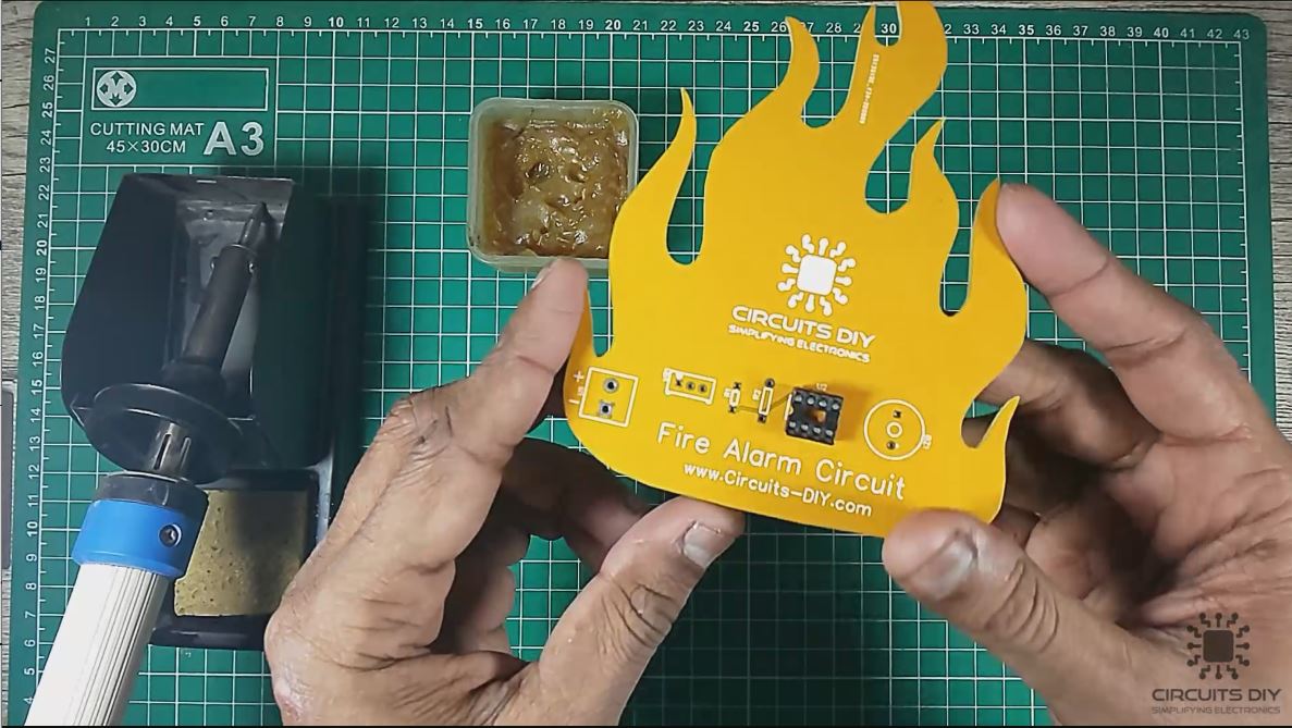
Useful Steps
1) Solder the IC jacket on the PCB board. After that, place the LM358 IC in the IC jacket.
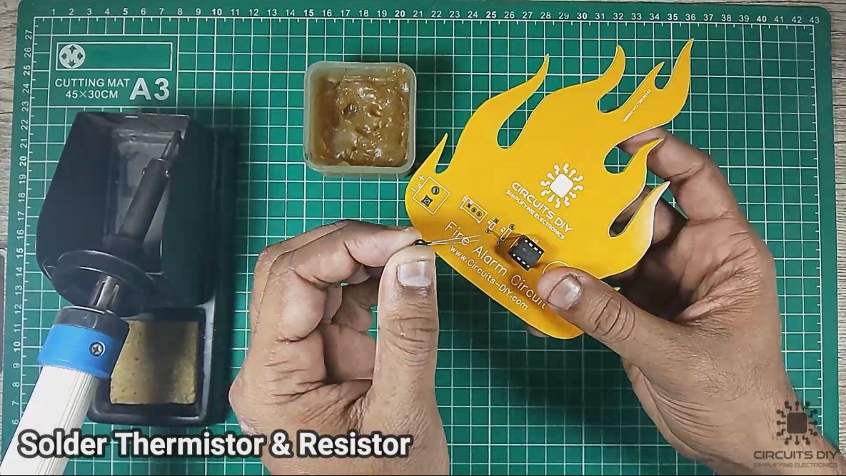
2) Solder the thermistor & the 10K resistor on the PCB board.
3) Solder the 5V Buzzer on the PCB board.
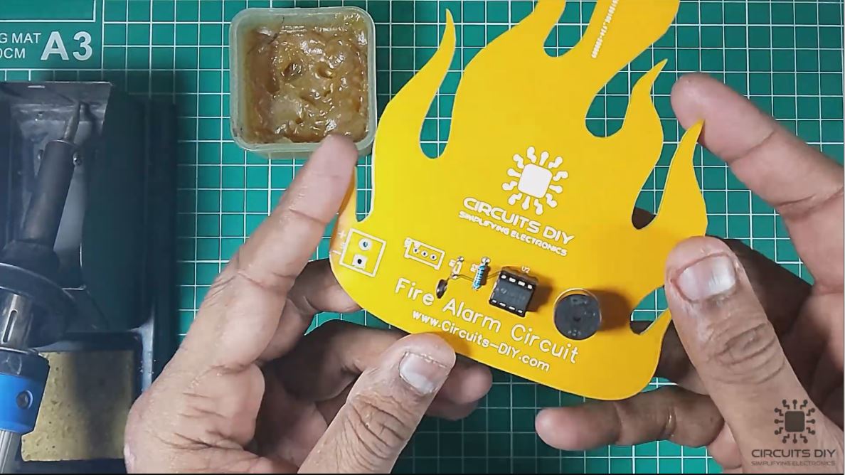
4) Solder the +ve & -ve terminals of the battery clip on the PCB board.

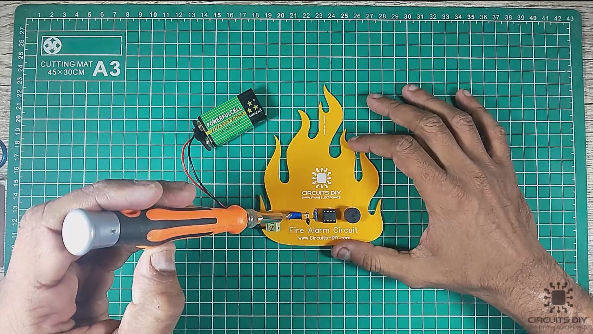
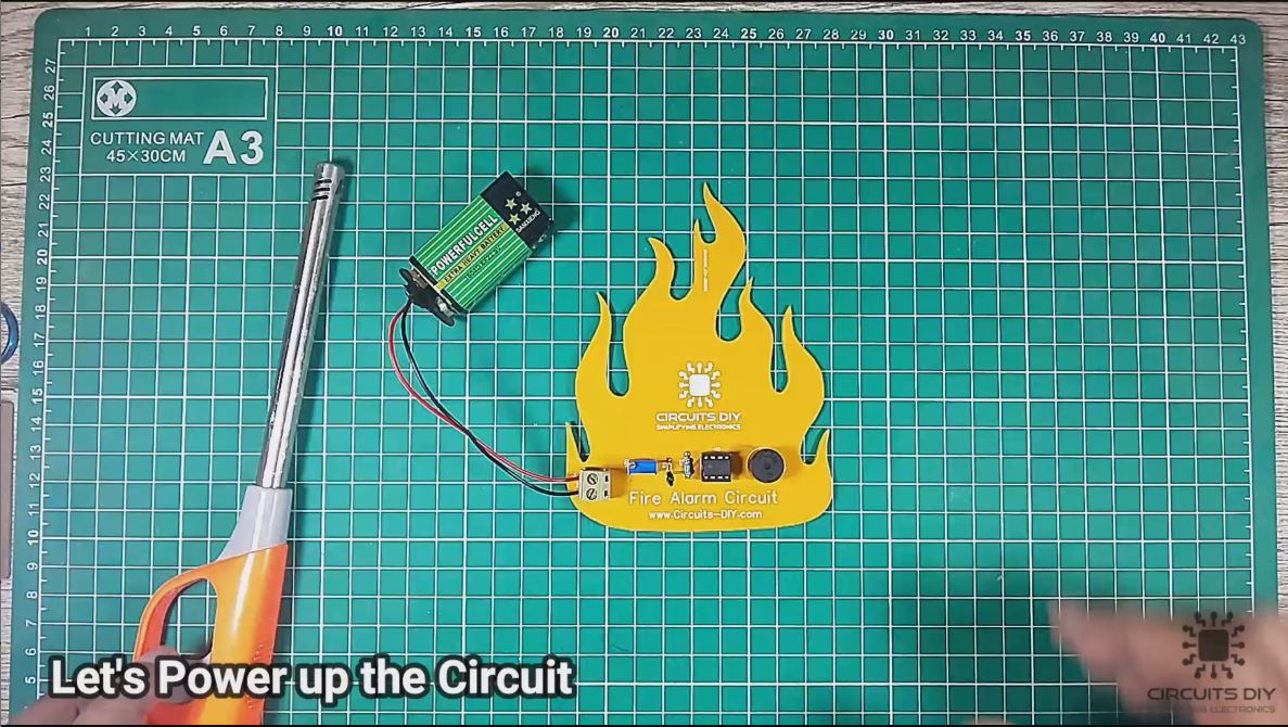
5) Power up the circuit using a 9V battery. After that, tune the resistance of the 10K preset pot.
6) Test the circuit.
Circuit Diagram For Fire Alarm
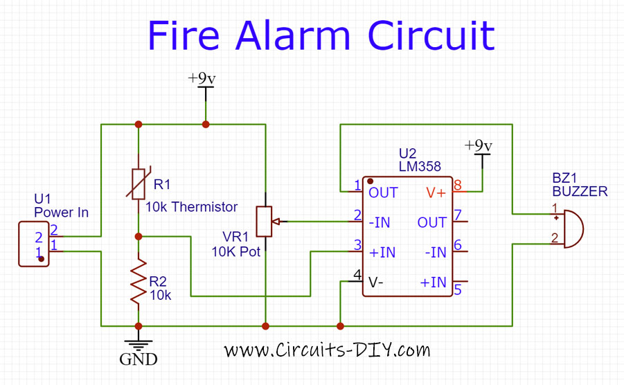
Working Explanation
The working of this circuit is pretty simple. On powering up the circuit and bringing a heating element close to it, the temperature around the thermistor begins to increase. Subsequently, the resistance of the thermistor decreases Due to which the output voltage of the voltage divider increases.
The output from the voltage divider then goes to the non-inverting of the LM358 Op-Amp. Since the voltage divider output is given to the non-inverting input of the IC, its value will become more than that of the inverting input. The amplifier output is then taken to a 5V buzzer which goes off. Indicating the presence of an ongoing fire. You can adjust the sensitivity of this fire alarm circuit by tuning the 10K preset pot. Alternatively, you can combine this configuration with various fire suppression systems such as automatic water sprinklers or foam extinguishing systems.
Applications
- A Fire alarm system plays an important role in industrial fire protection SOPs in order to preserve & sustain human life.
- They are used in homes in order to detect and timely alert the residents about the presence of a fire. So that the evacuation process can be initiated in a timely manner.
- They are also used in places such as criminal detention centers to keep the inmates from starting a fire that might hurt the prison guard personnel.
Gerber File
You can download the Gerber file for the above schematic from the link given below:
Related posts:
 How to make a Laser Security Alarm
 How to make Motor Controller by Using DPDT Relay
 Water Level Indicator Alarm
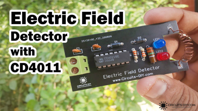 Electric Field Strength Detector Using CD4011BE IC
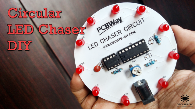 Circular LED Chaser using 555 timer & CD4017 - Electronics Projects
 How to Make Clap Switch | DIY Project | Home Automation | Electronics Projects