In this tutorial, we have to generate an input signal of frequency ‘f’ with an Astable multivibrator using a 555 timer IC. Now in phase two, we divided the input signal frequency by f/2 or f/4 with the counter IC 4017 for a decade. The RV1 Potentiometer makes the input frequency for the adjustment of the output frequency can be switched to f/2 and f/4 by using the SPDT switch.

Hardware Component
The following components are required to make Frequency Divider Circuit
| S.no | Component | Value | Qty |
|---|---|---|---|
| 1. | LEDs | – | 1 |
| 2. | IC | CD4017 | – |
| 3. | SPDT switch | – | 1 |
| 4. | Capacitor | 4.7uF, 10nF | 1 |
| 5. | Potentiometer | 50k | 1 |
| 6. | IC | NE555 Timer | 1 |
| 7. | Battery or supply | 9V | 1 |
| 8. | Bread Board | – | 1 |
| 9. | Voltage Regulator | LM7805 | 1 |
| 10. | Resistor | 10K, 47k ohm, 330k ohm, 220k ohm | 1 |
CD4017 Pinout
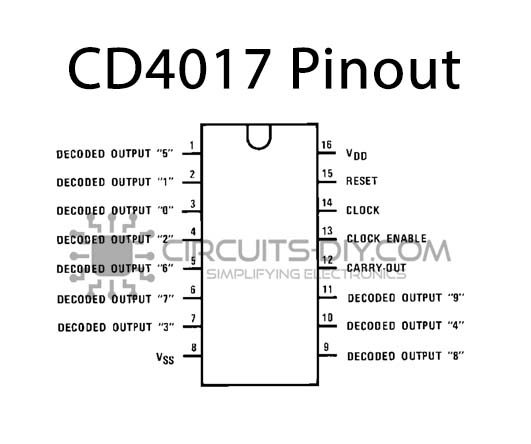
For a detailed description of pinout, dimension features, and specifications download the datasheet of CD4017
NE555 IC Pinout

For a detailed description of pinout, dimension features, and specifications download the datasheet of NE555 IC
LM7805 Pinout
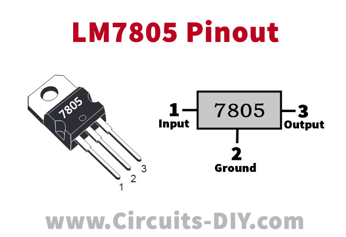
For a detailed description of pinout, dimension features, and specifications download the datasheet of LM7805
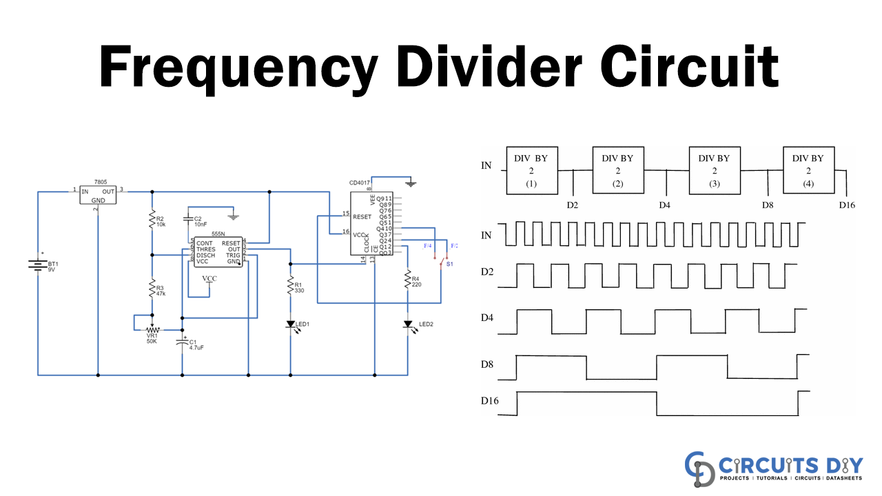
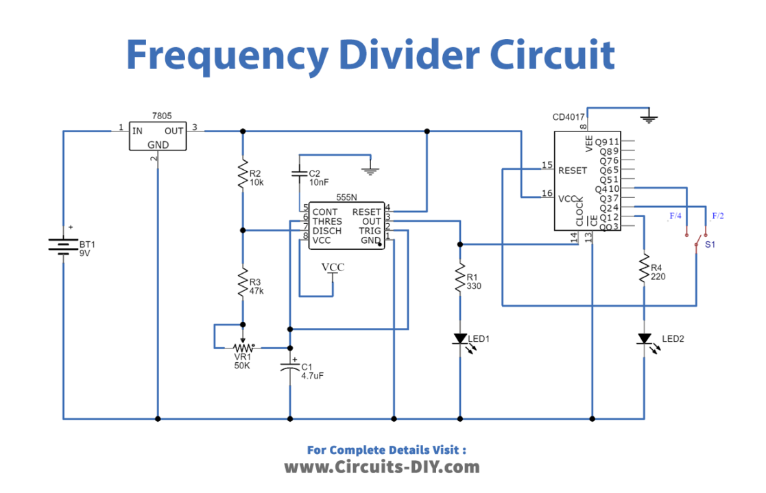
Frequency Divider Circuit
Circuit Operation
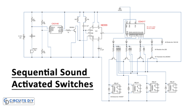
We used a 555 timer IC for generating an input frequency signal on this frequency divider circuit. In this case, a 10k (R2) resistor connected between Vcc and Pin 7th of 555 Timer (U1). Then between pins 7 and 6, we connected a 47k (R3) resistor and a 50k Pot (RV1). Pin 2 is shorted with pin 6, and the C1 capacitor 4.7uF is connected to pin 2 or 6 as far as the ground is concerned. Pin 1 is directly connected to the ground and pin 4 and even pin 8. This 555 timer’s output pin is connected by an LED D1 resistor of 330ohm and connected to a 4017 counter IC clock pin. LED D1 will indicate the frequency of the input signal.
4017 Counter IC divides the frequency by f/2 and f/4. For frequency selection, an SPDT switch is used. A LED D2 is connected to pin 2 of IC 4017 by a 220 Ohm resistor, which shows the divided frequency. Meaning LED D1 blinks with frequency f and LED D2 blinks with frequency f/2 or f/4 depending on the SPDT switch position. For voltage control, a 7805 IC is used. Finally, to control the circuit, we connected a 9V battery.
Applications and Uses
- Frequency Dividers are the circuits that divide the input frequency by n which means, that when the frequency “f” signal is given, the output will be divided by frequency “f/n.”
- 4017 Counter IC divides the frequency of f/2 and f/4.