Disasters and mishaps arrive when you are least expecting them. In today’s day & age, proper home security is a must for everyone. Smart door locks function as the very first step in an effective home security setup. In today’s article, we will look into a step-by-step process on ‘How How To Make A Smart Door Lock’ using An IR Receiver & a Servo Motor.
Smart Door Lock
A smart door lock is an electronic and mechanical locking device that opens wirelessly with an authorized user’s authentication. In a smart home, smart door locks allow a homeowner to enter their home or provide others access without requiring a traditional key.
JLCPCB is the foremost PCB prototype & manufacturing company in china, providing us with the best service we have ever experienced regarding (Quality, Price Service & Time).
Hardware Components
The following components are required to make a Smart Door Lock Circuit
| S.no | Component | Value | Qty |
|---|---|---|---|
| 1. | IC | NE555 Timer | 1 |
| 2. | Op-Amp IC | LM358 | 1 |
| 3. | Transistor | 2n2222 | 2 |
| 4. | Servo Motor | SG-90 | 1 |
| 5. | Relay Switch | SPDT/5V | 1 |
| 6. | IR Emitter LED | 5mm/3.5V | 1 |
| 7. | IR receiver | TSOP1738 | 1 |
| 8. | LED | 5mm | 1 |
| 9. | Potentiometer | 10K | 1 |
| 10. | Capacitors | 100nF | 2 |
| 11. | Resistors | 10K, 68K, 33K, 4.7K, 1K, 560 Ohm, 220 Ohm | 9 |
| 12. | Soldering Iron | 45W – 65W | 1 |
| 13. | Diode | 1N4007 | 1 |
| 14. | Soldering Wire with Flux | – | 1 |
| 15. | Veroboard | – | 1 |
| 16. | DC Battery with Clip | 9V | 1 |
| 17. | Male Header pins | – | 1 |
| 18. | Jumper Wires | – | as per need |
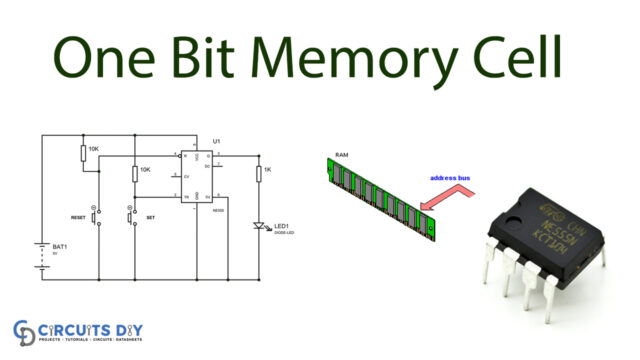
NE555 IC Pinout
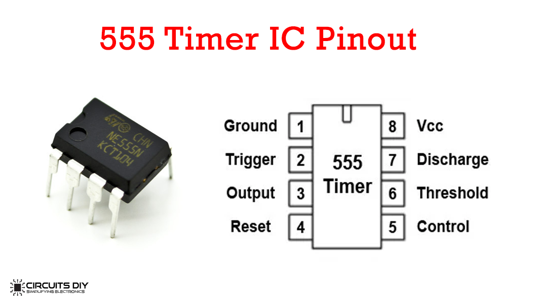
For a detailed description of pinout, dimension features, and specifications download the datasheet of 555 Timer
LM358 Pinout

For a detailed description of pinout, dimension features, and specifications download the datasheet of lm358
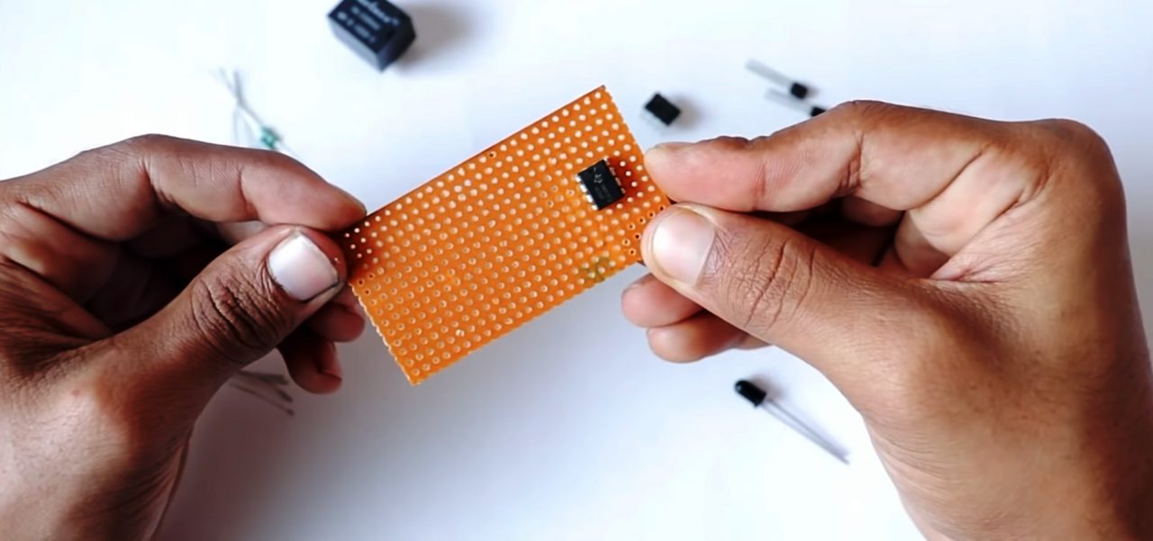
Useful Steps
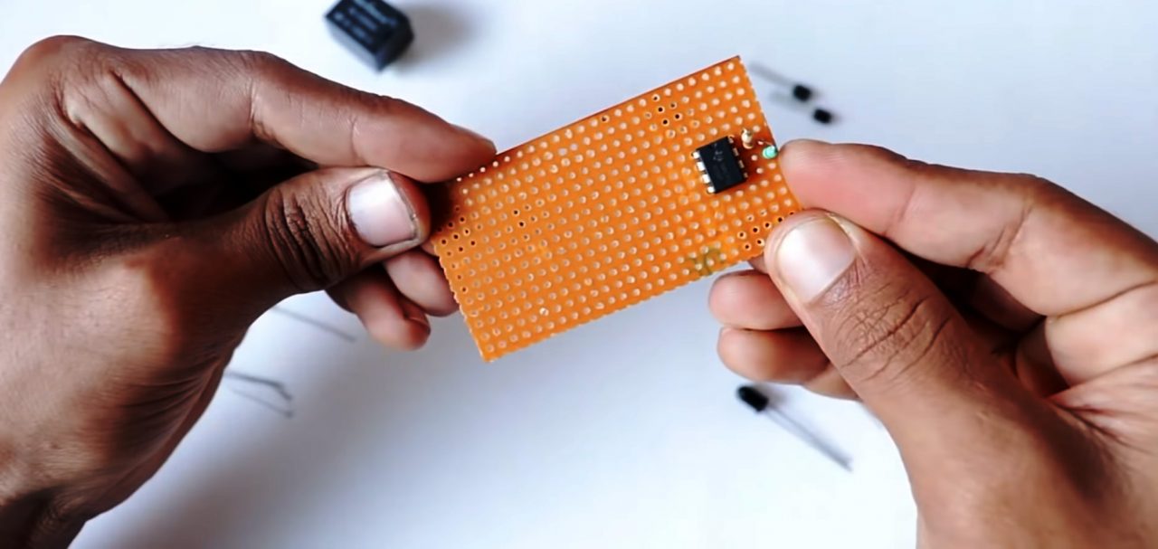
1) Solder the pins 4 & 8 of the 555 timer IC on the Vero board.
2) Solder a 33K Ohm resistance between pin 7 & pin 8 of the timer IC. After that solder a 68K resistor between pins 6 & 7 of the timer IC.
3) Solder two 100 pF capacitors from pin 2 to pin 1 and pin 1 to pin 5 of the timer IC.
4) Solder the emitter of the 2n2222 transistor to pin 1 of the IC. After that, solder a 4.7K resistor between pin 8 & the collector of the transistor.
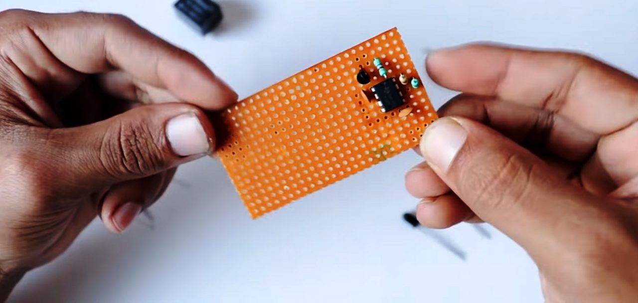
5) Connect a 1K resistance between pin 3 & the base of the transistor.

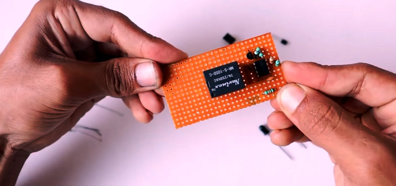
6) Solder a 5V relay on the Vero board & solder a 10K resistor between pin 6 & NO terminal of the relay.
7) Solder male headers for servo & LM358 Op-Amp on the Veroboard

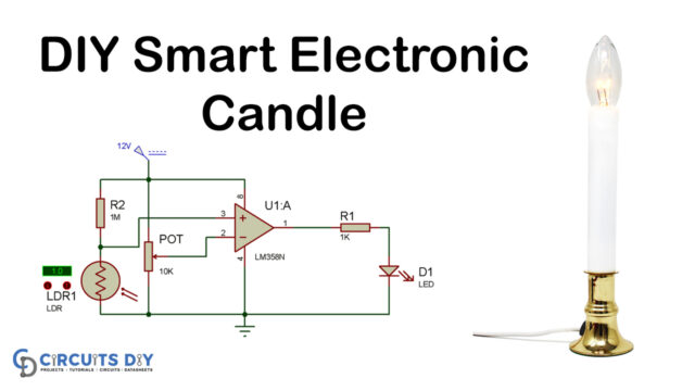
8) Solder the 10K pot & a 10K resistor between pins 4 & 3 of the Op-Amp.
9) Solder a 1N4007 Diode between relay coil pins. After that, solder it to the collector of the 2n2222 transistor with an emitter soldered to pin 4 of the LM358 IC.

10) Connect a 220 Ohms resistor from pin 1 of the op-amp to the +ve terminal of the LED & connect a 560 Ohm resistor from pin 1 of the op-amp to the base of the transistor. Connect the LED +ve to pin 1 & -ve to pin 4 of the op-amp.
11) Connect a 220 Ohm resistance on pin 4 of the op-amp.

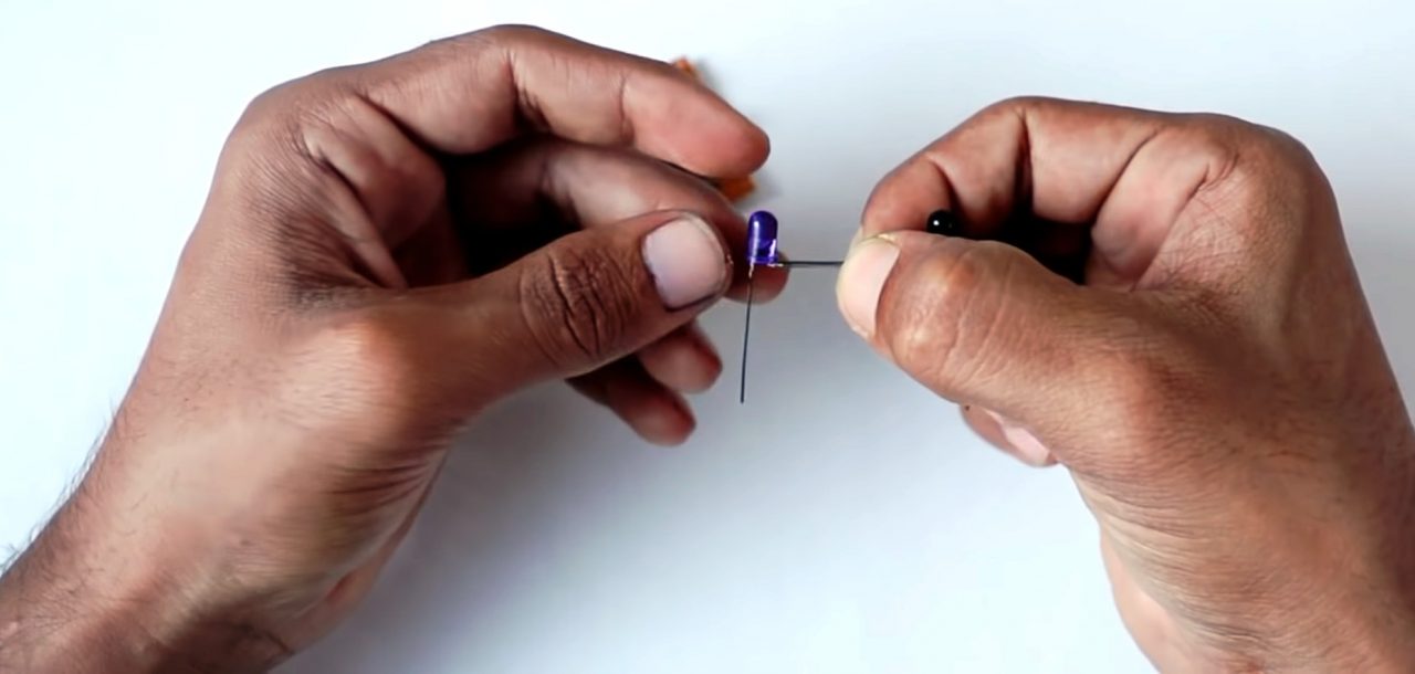
12) Join the IR transmitter LED & receiver in series.
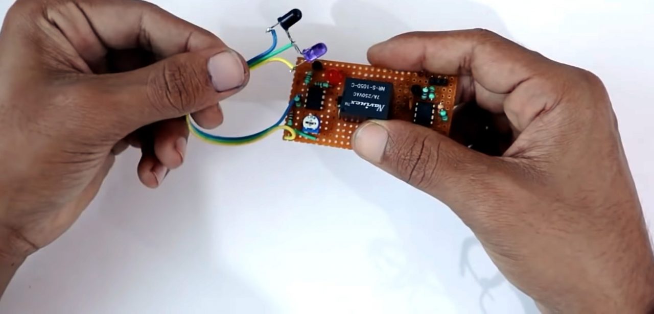
13) Connect the Vcc & GND for Both ICs. Connect the servo to the headers & test the circuit.
Working Explanation
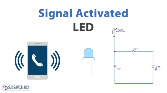
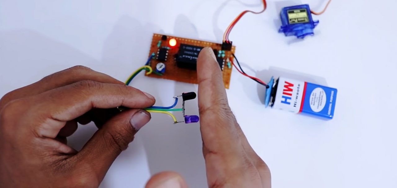
The working of this circuit is pretty simple. In order to use the lock you simply need to reflect the IR rays on the receiver by using your hands, the receiver feeds the output to the inverting input of the op-amp. The op-amp generates an amplified output with respect to the preset of the 10K pot. The output of the op-amp acts as the control signal to the base of the 2n2222 transistor. The resultant collector output picks the coil of the relay & makes the connection to the 555 timer circuit.
The output of the SPDT relay, connected to the TRIG pin of the 555 timers IC results in an output that goes to the base of the second 2n2222 transistor. The collector output signal pin of the servo & triggers the motion of the servo, enabling the door to be unlocked.
Applications
- An integral part of home security systems.
- Also used in places such as security locks & vaults in banks & ATMs.