Introduction
Many times you may have seen that LEDs are getting used for the decoration purpose of different events. LED lights, LED lamps, and LED strips are widely utilized. Hence, they can be designed in different ways through the pulse generator. Circuit designers use different types of ICs and sometimes microcontrollers to generate the pulses. Thus, giving them different effects that make them more beautiful. Hence, we have decided to make a lamp pulse circuit to show that in this tutorial. To make our circuit, we are utilizing the LM358 operational amplifier IC. The IC is easily available in the market and is highly affordable.
Hardware Required
| S.no | Component | Value | Qty |
|---|---|---|---|
| 1. | IC | LM358 | 2 |
| 2. | Transistor | BC547 | 1 |
| 3. | LED | – | 3 |
| 4. | Capacitor | 1µF/16V | 1 |
| 5. | Resistor | 4.3KΩ, 1MΩ, 20KΩ, 10KΩ, 100Ω | 2, 1, 1, 1, 1 |
| 6. | Battery | 6V | 1 |
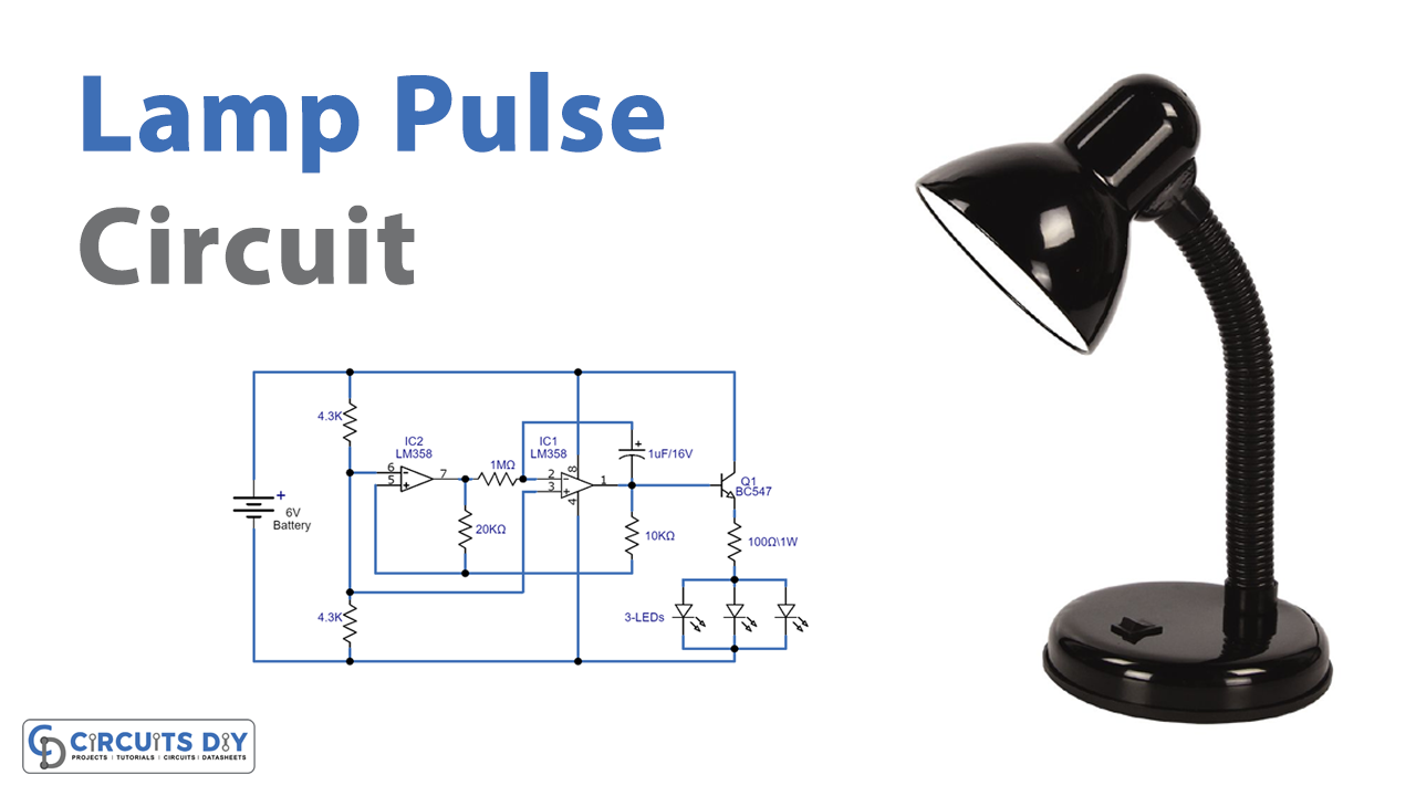
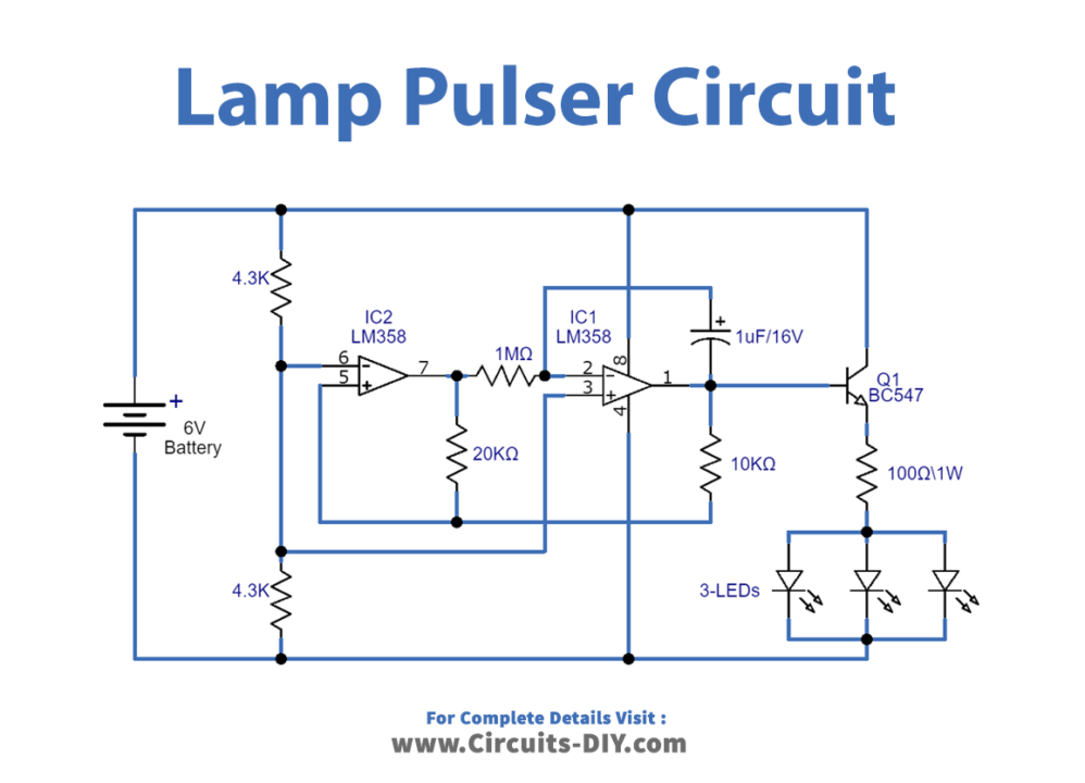
Circuit Diagram
Working Explanation
Our lamp pulse circuit is constructed with the help of LM358 Ic, which contains Dual high-gain operational amplifiers. The voltage divider input is given at the inverting input pins of both the amplifiers, that is pin 2 and pin 5, through the help of resistors R1 and R2. The output of the first amplifier is provided to the non-inverting input pin of the second amplifier with the help of resistor R4. Hence you can observe the final output at pin 7 of an IC. The output is in the form of a triangular wave, given to the base of the transistor which triggers the transistor and gives the amplified output to the LEDs. As a result, LEDs start to blink.
Application and Uses
- To generate pulses.
- For the decoration purpose of different events.
- To check the triangular pulses on different timing values.