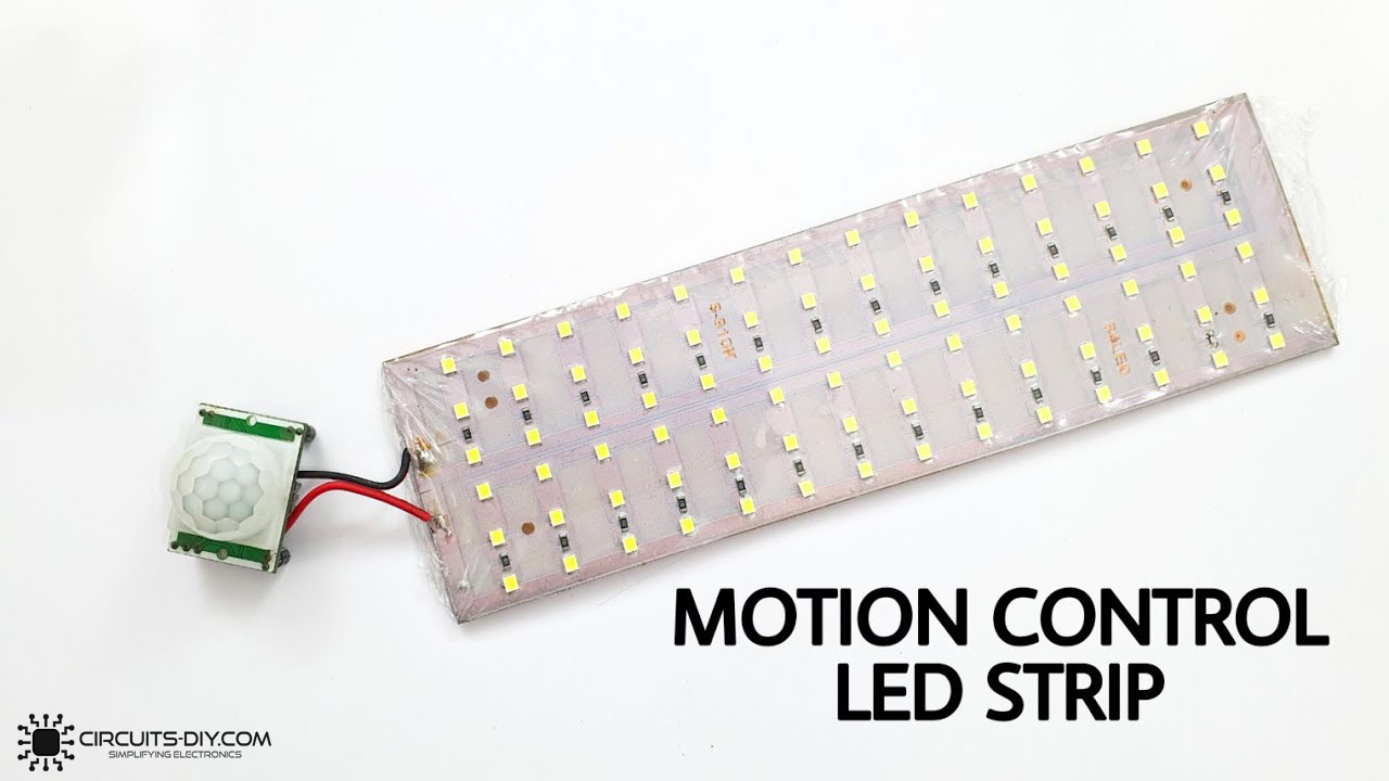
Motion-controlled LED strips & lights exude a sense of safety and security to any property, whether it be a common household or a professional work setup. With the help of motion-controlled lighting solutions, you will never have to worry about having to watch your step in the dark again. So, in today’s tutorial, we will go over a step-by-step process on how you can build your very own Motion Controlled LED Strip Using a Pyroelectric (PIR) Motion Sensor & a small number of other electronic parts.
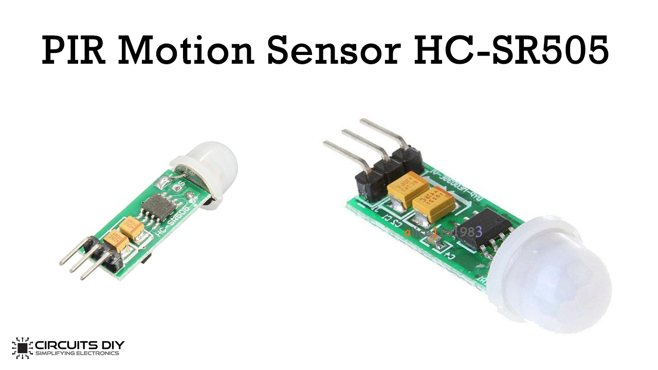
The heart of this project is a PIR motion sensor. A Pyroelectric Infrared or PIR motion sensor allows you to detect whether a human has moved in or out of the sensor’s range. PIR motion sensors are small, inexpensive, low-power, easy to use, and reliable. They are made from an array of solid-state sensors, designed using pyroelectric materials that generate a Vsig when exposed to heat. They are used in thermal sensing applications, including security sensors and motion detectors.
JLCPCB is the foremost PCB prototype & manufacturing company in china, providing us with the best service we have ever experienced regarding (Quality, Price Service & Time).
Hardware Required
The following components are required to make Motion Controlled LED Circuit
| S.no | Component | Value | Qty |
|---|---|---|---|
| 1. | PIR Motion Sensor Module | 12V | 1 |
| 2. | LED strip | 12V/5mm | 1 |
| 3. | NPN Power Transistor | TIP31, 3A, 100V | 1 |
| 4. | Soldering Iron | 45W – 65W | 1 |
| 5. | Soldering Wire With Flux | – | 1 |
| 6. | DC Power Jack | 3.5mm | 1 |
| 7. | DC Battery | 12V | 1 |
| 8. | Jumper Wires | – | As per need |
PIR Motion Sensor
Useful Steps
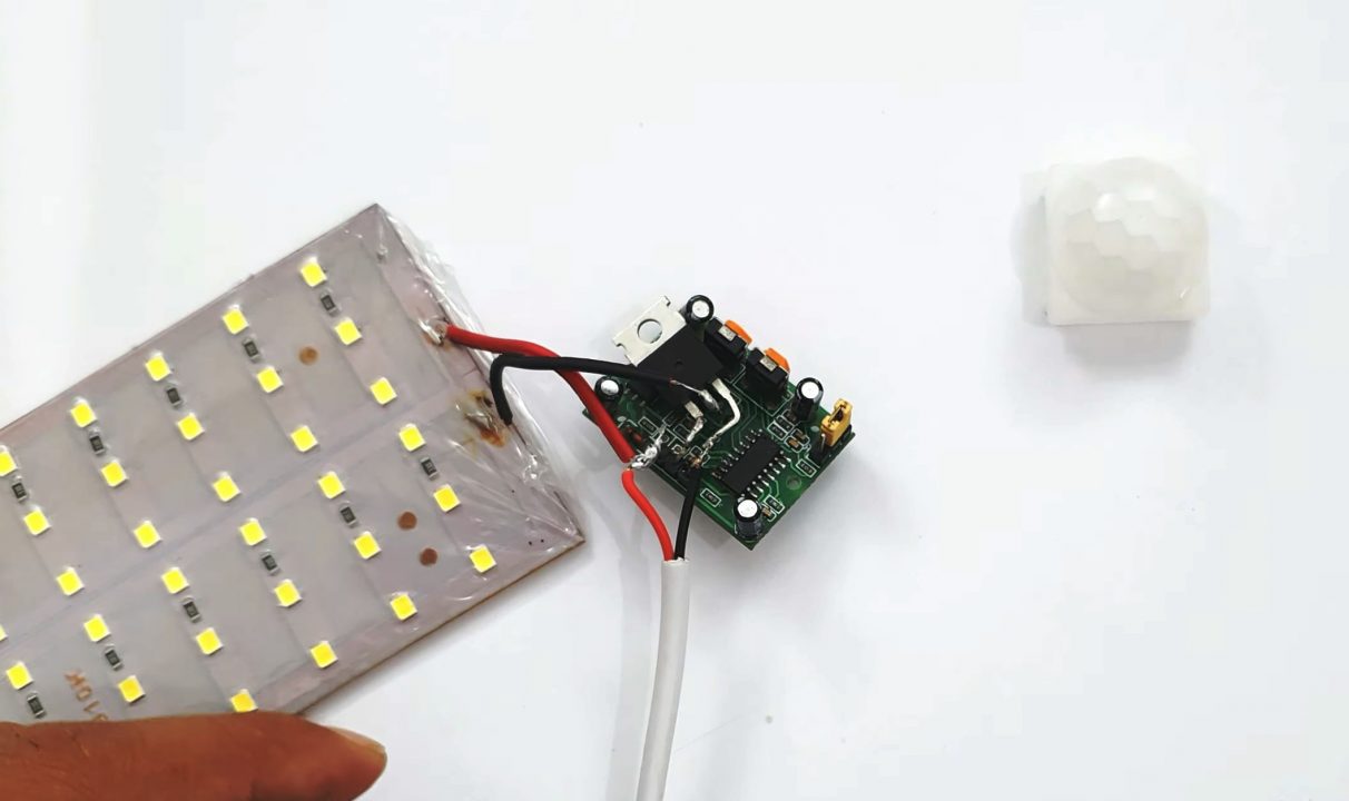
1) Solder the emitter terminal of the TIP31 transistor with the GND terminal of the PIR sensor module. After that solder the base terminal of the transistor with the signal pin(out) of the PIR sensor.,

2) Now, solder the positive terminal of the LED strip with Vcc of the PIR sensor & the negative terminal with the collector of the transistor.
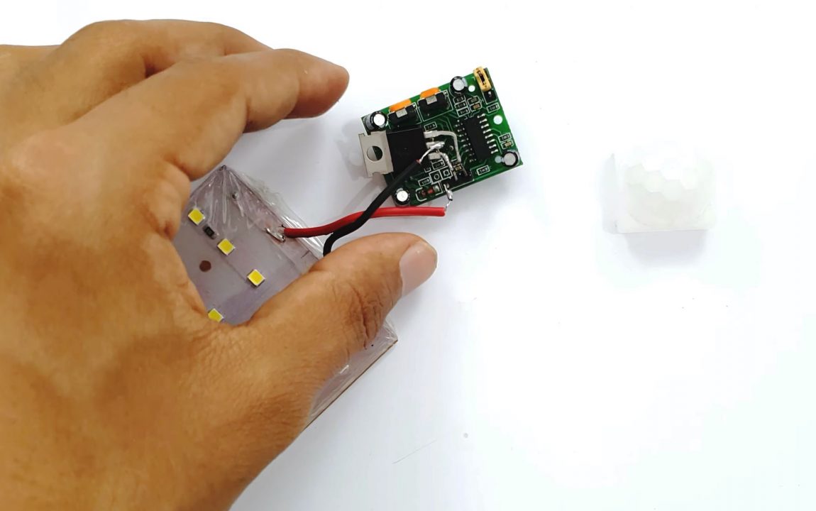
3) Solder the positive & negative terminals of the DC power jack with Vcc & GND terminals of the PIR Sensor module.
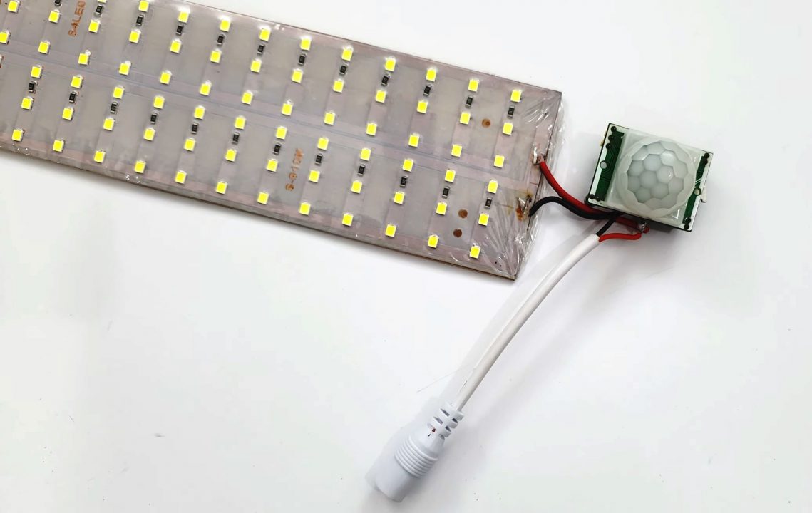
4) Firmly seal the sensor’s plastic covering over the sensing element. After that, power up & test the circuit.
Working Explanation
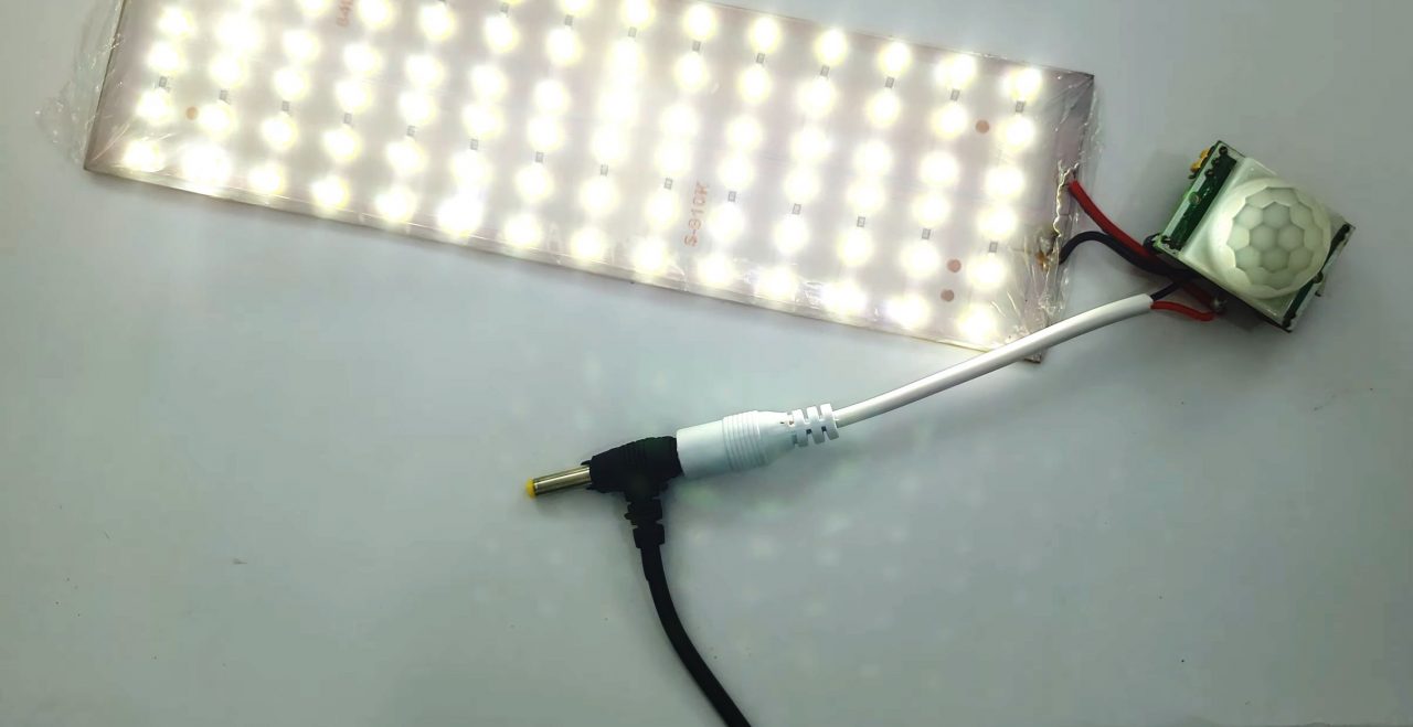
This circuit basically utilizes the sensing capability of a PIR sensor module & combines it with the high switching application of a power transistor. Here we have simply connected a TIP31 power transistor with the Output (Signal) terminal of the PIR sensor module. On powering on the circuit, whenever any thermally charged body moves in front of the sensor, the sensor sends a control signal to the base of the transistor.
On receiving the signal, the collector output from the transistor triggers the LED strip to switch ON. When the body obstructing the PIR sensor’s line of field is removed, the control signal at the base of the transistor diminishes, which in turn signals the LED strip to switch OFF.
Applications
- Motion-controlled LED lights are generally used outside of homes and buildings, in order to sound an alarm or to turn on a light so to announce a person’s presence.