
Introduction
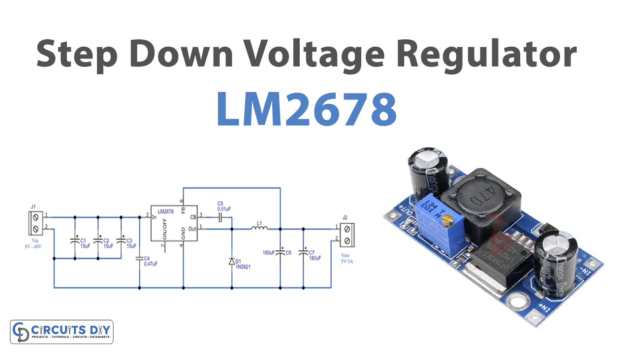
The major function of the voltage regulator is to drop the higher voltage into lower or the increase lower voltages into higher, that’s why known as step down voltage regulator or step-up regulator respectively. However, many other types of voltage regulators also have been designed by circuit designers and engineers. For example, some regulators also convert the AC voltages into high or low DC voltage. But. this tutorial is not about those types of regulators but particularly about the step-down voltage regulator.
In this tutorial, we are going to Make a “Step Down Voltage Regulator Circuit”. The circuit is easier to make but requires little knowledge of electronics.
Hardware Components
The following components are required to make Voltage Regulator Circuit
| S.no | Components | Value | Qty |
|---|---|---|---|
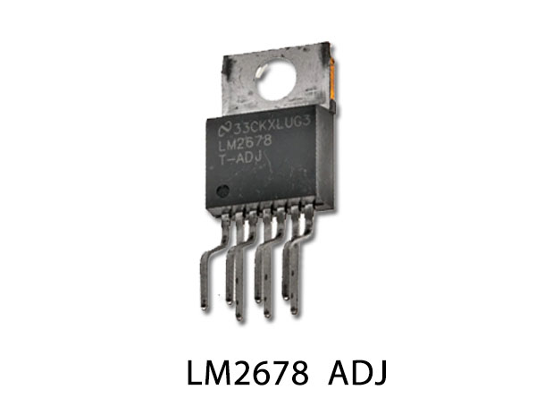
| 1. | IC | LM2678 | 1 |
| 2. | Inductor | – | 1 |
| 3. | Diode | 1N5821 | 1 |
| 4. | Electrolytic Capacitor | 15µF, 180µF | 3,2, |
| 5. | Ceramic Capacitor | 0.1nF, 0.47uf | 1 |
| 7. | 2-Pin Connector | – | 2 |
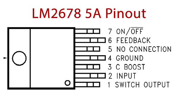
LM2678 Pinout
For a detailed description of pinout, dimension features, and specifications download the datasheet of LM2678
Voltage Regulator Circuit
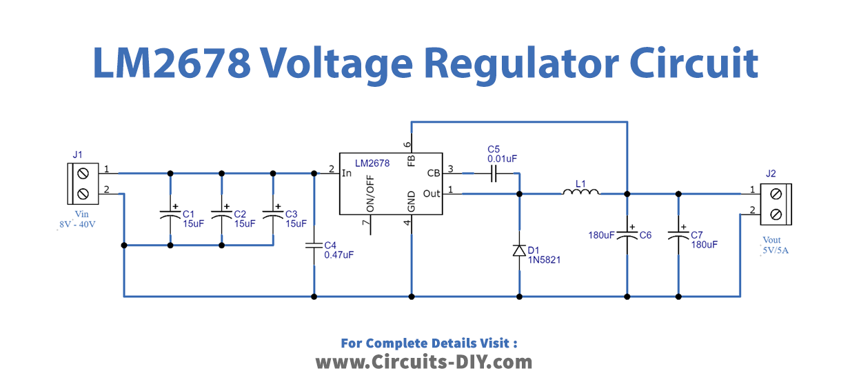
Working Explanation
For this circuit, we have used the voltage regulator LM2678 IC. The IC has an internal 5 Volt Regulator, 260KHz Oscillator, and it also contains the block for thermal shut down. The input is applied to pin 2, which is the input pin of an IC. Pin four is for the ground. The capacitors are used for filtering purposes. Pn 3 is for the bootstrap capacitor connection. After these connections, you would get the 5V voltage with 5A of current at the output. Connect any load of this voltage.
Application and Uses
- It can be used in amplifier circuits.
- It can also be utilized in power supply applications.
- Any electronic device or circuit that needs precise voltage.
Related posts:
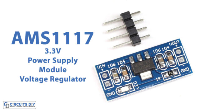 AMS1117-3.3V Power Supply Module Voltage Regulator
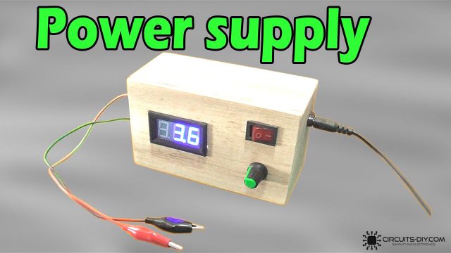 Simple Adjustable Power Supply Using LM317 Voltage Regulator
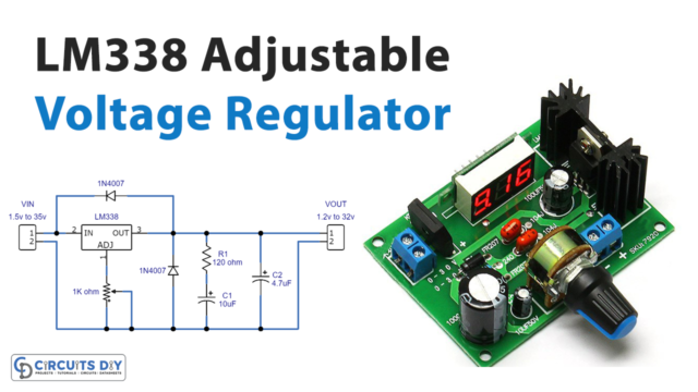 Adjustable Voltage Regulator Circuit Using LM338
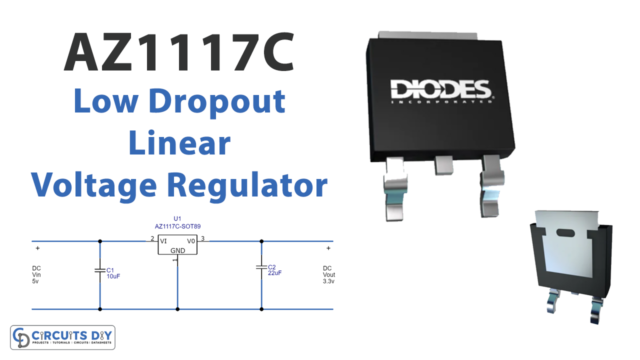 AZ1117C Low Dropout Linear Voltage Regulator Circuit
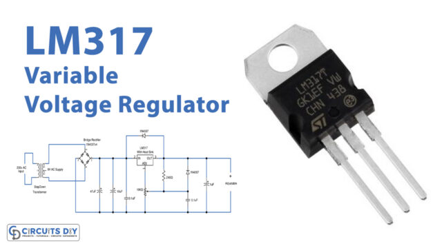 Variable LM317 Voltage Regulator Circuit
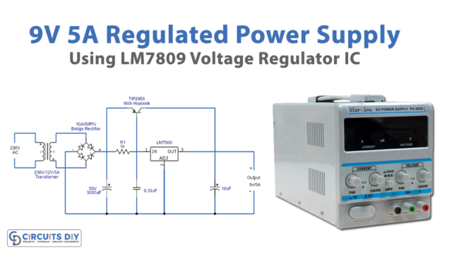 9V/5A Regulated Power Supply Using LM7809 Voltage Regulator


