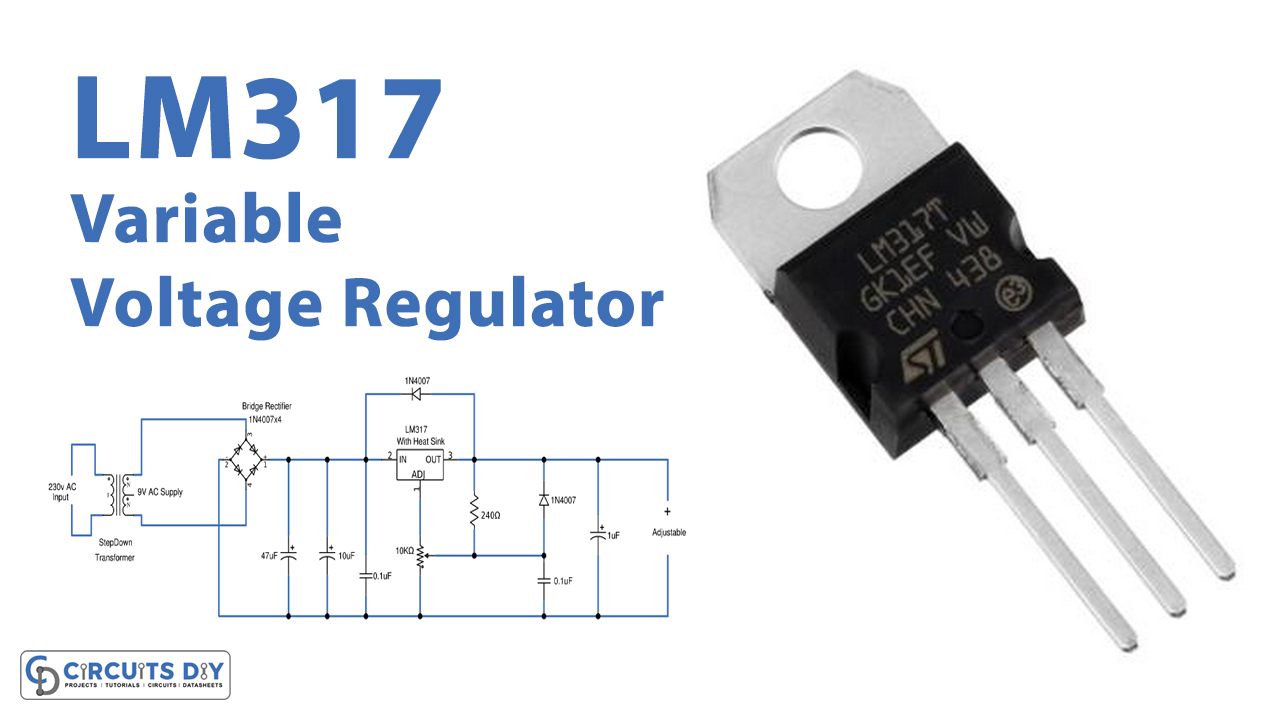
In this tutorial, we are going to make a “Variable LM317 voltage regulator circuit”.
As we know a regulated power supply is essential for several electronic devices due to the semiconductor material employed in them having a fixed rate of current as well as voltage. The device may get damaged if there is any deviation from the fixed rate. So, whenever we need a constant and specific value of voltage without fluctuation, we use a voltage regulator IC. They provide a fixed-regulated power supply. We have 78XX (7805, 7806, 7812, etc.) series voltage regulators for positive power supply and 79XX for negative power supply. But what if need to vary the power supply voltage, so here we have variable voltage regulator IC LM317.
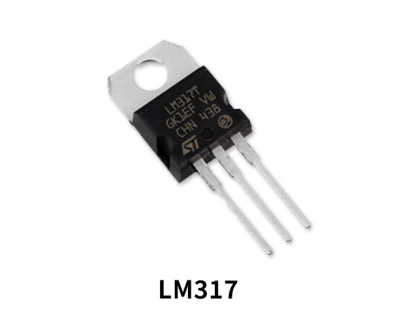
LM317 is a popular adjustable positive voltage regulator in this tutorial we will show you how to get the variable regulated Voltage from the LM317 IC. With a small circuitry attached with LM317, we can get the variable voltage up to 37v with 1.5A max current. The output voltage is varied by varying the resistor connected to LM317’s adjustable pin. LM317 IC includes current limiting, thermal overload protection, and safe operating area protection. Overload protection remains functional even if the ADJUST terminal is disconnected. This IC comes in different package sizes, depending on circuit design and thermal consideration we can choose LM317.
Hardware Components
The following components are required to make Voltage Regulator Circuit
| S.no | Component | Value | Qty |
|---|---|---|---|
| 1. | Step down transformer | 0-9V 1 amps | 1 |
| 2. | Bridge Rectifier Diode | 1N4007 | 6 |
| 3. | IC | LM317 | 1 |
| 4. | Variable Resistor | 10KΩ | 1 |
| 5. | Resistor | 240Ω | 1 |
| 6. | Ceramic Capacitor | 0.1uF | 2 |
| 7. | Electrolytic Capacitor | 47uF, 10uF, 1uF | 1,1,1 |
LM317 Pinout
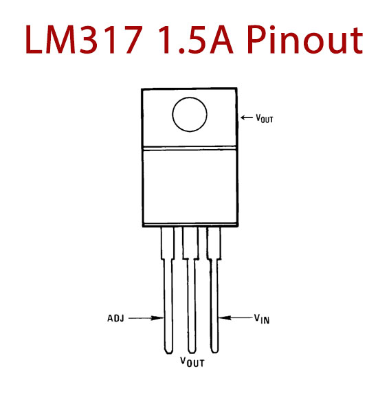
For a detailed description of pinout, dimension features, and specifications download the datasheet of LM317
Voltage Regulator Circuit

Working Explanation
As we can see this circuit design starts with a step-down transformer, which is used to step-down supply AC. And then the bridge rectifier module is made up of diodes to rectify AC into DC. As you know the output of the bridge rectifier is pulsating DC although the waveform can be considered to be a DC voltage since the output polarity does not invert itself, the large ripples that exist in the output make it almost impossible to be used in any powering applications. So, it is to remove these ripples that the smoothing capacitors C1 and C2 are used. C3 is used to avoid ripples if filtering is performed at some distance from the regulator. Regulator IC LM317 adjust pin connected with variable Resistor and output through feedback resistor R1. At the output diode, D2 provides reverse voltage protection.
LM317 Regulates input DC supply from Rectifier and takes feedback from the output through D1 and adjustable pin takes feedback voltage and current through variable Resistor and R1 resistor. The capacitance C4 bypassing the ADJUST pin to the ground will improve the ripple rejection capability. The capacitance C5 is very important in the circuit because without this capacitance, the LM317 tends to act as an oscillator in the Mhz ranges. It also has the added advantage of improving the transient response of the circuit.
Hence the output at the load appears constant and the output voltage range can be adjusted by RV1. Use heatsinks when you expect to obtain output voltage beyond 15V. Here we designed this variable power supply unit to give 1.5V to 9V regulated output voltage, you can apply your desired input supply up to 37V.
Applications
It can also be used as a fixed voltage regulator, current limiter, Battery charger, AC voltage regulator, and even as an adjustable current regulator.
Related posts:
 AMS1117-3.3V Power Supply Module Voltage Regulator
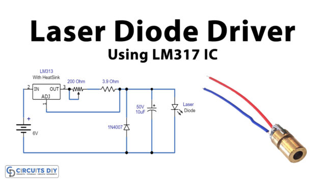 Laser Diode Driver Using LM317 Voltage Regulator IC
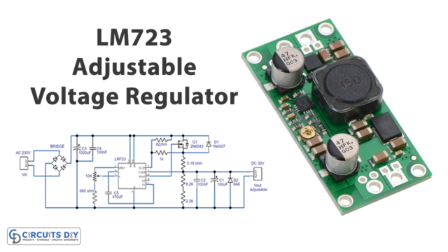 LM723 Adjustable Voltage Regulator 30V Circuit
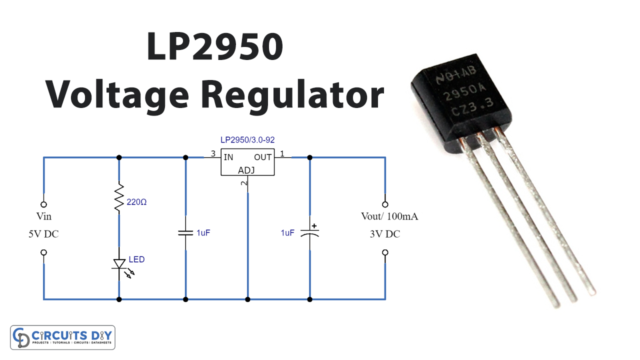 LP2950 Adjustable Micropower Voltage Regulator Circuit
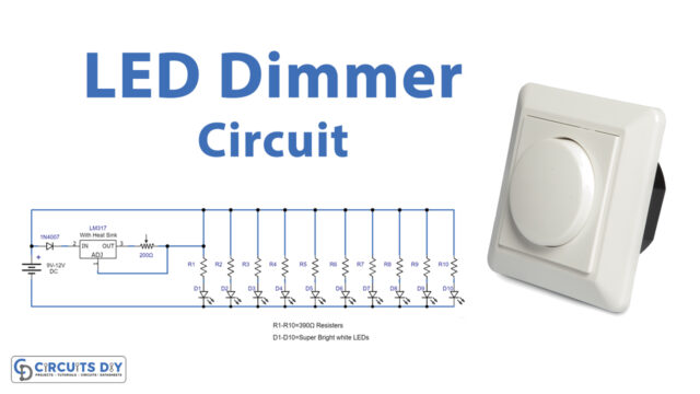 LED Dimmer Circuit Using LM317 Voltage Regulator IC
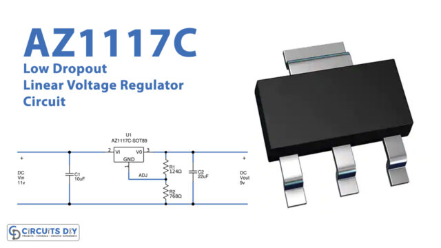 AZ1117C Low Dropout Linear Voltage Regulator Circuit