
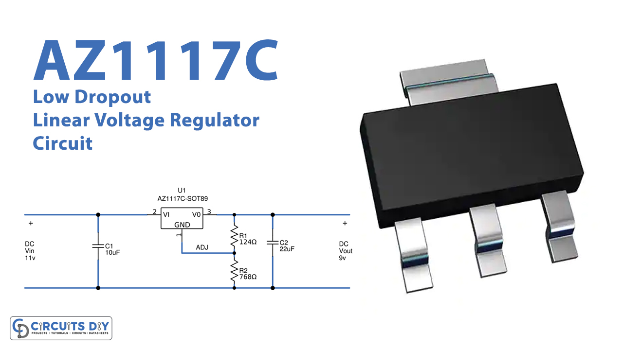
In this tutorial, we are going to make an “AZ1117C Low Dropout Linear Voltage Regulator Circuit”.
It is convenient for a battery-powered design that we should look for a low dropout voltage regulator because by picking the Low dropout regulators we can improve the operation time of the battery. A voltage regulator is used for two reasons to regulate or vary the output voltage of the circuit to keep the output voltage constant at the desired value despite variations in the supply voltage or the load current. Whilst a low-dropout regulator (LDO regulator) is a DC linear voltage regulator that can regulate the output voltage even when the supply voltage is very close to the output voltage. Low-dropout (LDO) regulators operate similarly to all linear voltage regulators.
The main difference between LDO and non-LDO regulators is their schematic topology. Here we designed a low dropout linear voltage regulator circuit by using AZ1117C to give Adjustable and fixed output voltage. AZ1117C from Diodes Incorporated is a low dropout three-terminal regulator. It is optimized for low voltage design where transient response and minimum input voltage are critical. It provides current limit and thermal shutdown (On-chip thermal shutdown protects against a combination of high current and ambient temperature that would create excessive junction temperature). It has trimmed bandgap references to give accurate output voltage. The AZ1117C is available in the industry-standard TO252-2 Series (Including TO252-2 (3), TO252-2 (4), and TO252-2 (5)), SOT89, and SOT223 power packages.
Hardware Components
| S.no | Component | Value | Qty |
|---|---|---|---|
| 1. | IC | AZ1117C | 1 |
| 2. | Capacitor | 10µF, 22µF | 1,1 |
| 3. | Resistor | 124Ω, 768Ω | 1,1 |
| 4. | Connecting Wires | – | 1 |
| 5. | Power Supply | – | 1 |
AZ1117C Pinout
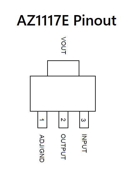
For a detailed description of pinout, dimension features, and specifications download the datasheet of AZ1117C
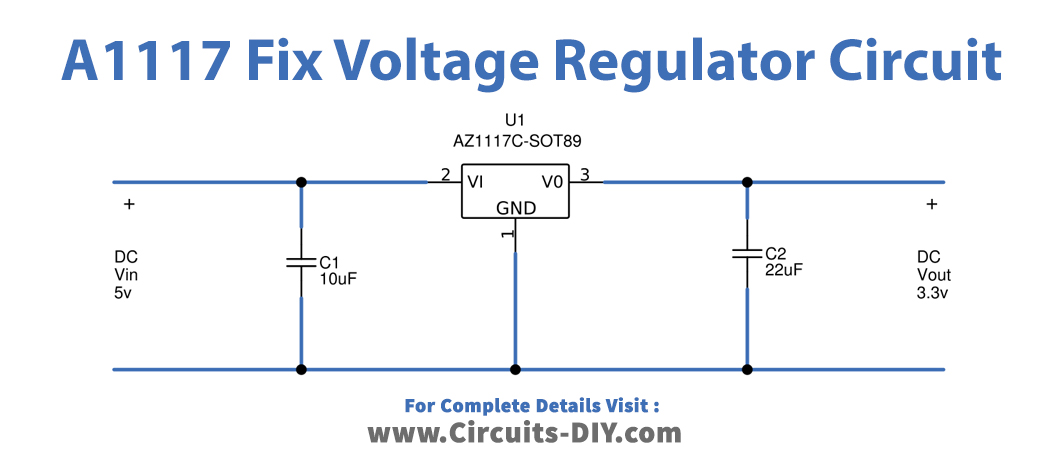
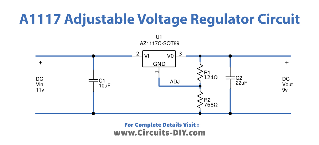
Linear Voltage Regulator Circuit
Adjustable Regulator Calculation

Working Explanation
We can use AZ1117C as an Adjustable voltage Regulator or a Fixed one by using a few external resistors and capacitors depending on our need. AZ1117C comes in different packages, it can take input voltages up to 18 volts and gives an output voltage range from 1.5V to 10V. The AZ1117C is available in 1.2V, 1.5V, 1.8V, 2.5V, 3.3V, 5.0V fixed output voltage versions and ADJ output voltage versions. The fixed versions integrate the adjusted resistors. It is also available in an adjustable version which can set the output voltage with two external resistors.
First, we need to place a voltage divider setup using two resistors for an adjustable voltage regulator design using AZ1117C. Now to make a variable voltage regulator connect the Adj pin of AZ1117C to the voltage divider, where we can get the desired output voltage by changing the value of R1 and R2 resistors. Here C1 and C2 capacitors are used for filter purposes.
Whilst we need only voltage filter Capacitors C1 and C2 for fixed voltage regulator design. By choosing AZ1117C fixed voltage (1.2V, 1.5V, 1.8V, 2.5V, 3.3V, 5.0V) we can obtain accurate regulated output voltage.
Applications
The main applications are listed below.
- Cellular Telephones, Palmtop Computers, Laptop & Notebook
- Personal Electronics or Consumer Electronics
- Equipment with Battery-Powered
- Linear Power Supplies with High-Efficiency
- DC/DC Modules & SMPS Post-Regulator
- VPP Regulation or Switching & PCMCIA VCC
- The LDOs like Low-Noise & High-PSRR is used for Wireless & Wired Communications.
Related posts:
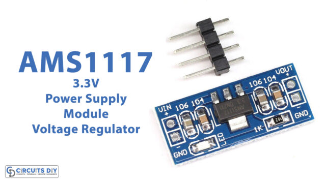 AMS1117-3.3V Power Supply Module Voltage Regulator
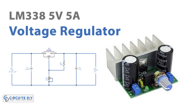 LM338 5 Volt 5 Amp Voltage Regulator
 Simple Adjustable Power Supply Using LM317 Voltage Regulator
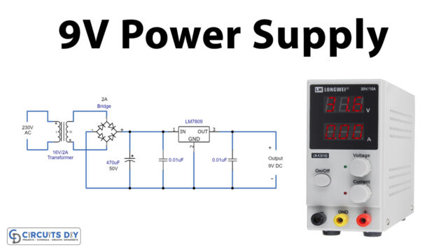 9V Power Supply Circuit Using LM7809 Voltage Regulator IC
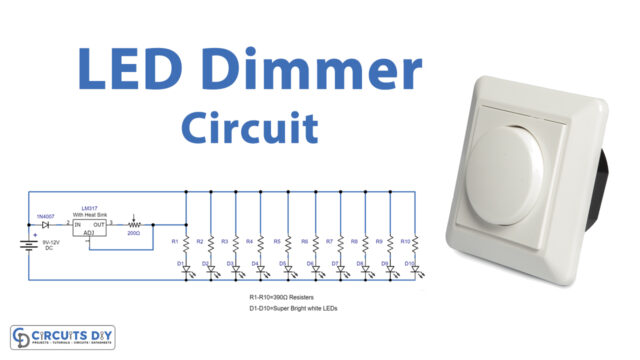 LED Dimmer Circuit Using LM317 Voltage Regulator IC
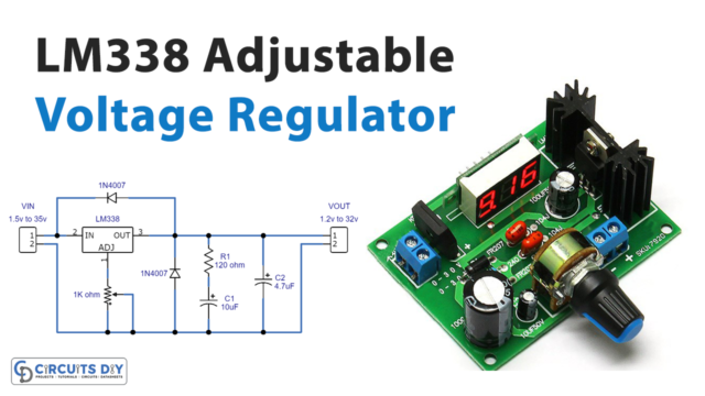 Adjustable Voltage Regulator Circuit Using LM338


