Introduction
In many electrical circuits, no voltage controllers are present there, hence if there is any change in the input voltage, it would definitely be expressed or appeared at the output. These types of circuits are mostly used for LED lights, DC motors, etc. Thus, we can say that unregulated voltage allows variation on the output side. But, for, any electronic devices like laptops, televisions, etc, these variations can be harmful because they can cause temperature variation, poor regulation, etc. So to overcome this circuits called voltage regulators are used. It reduces the ripples and fluctuations in the voltages. Different regulators come with different current and voltage readings. In this tutorial, we are going to discuss the “5 Volt 5 amp Voltage Regulator”
Hardware Required
| S.no | Component | Value | Qty |
|---|---|---|---|
| 1. | Voltage Regulator IC | LM338 | 1 |
| 2. | Ceramic Capacitor | 0.1µF, 1µF | 1, 1 |
| 3. | Potentiometer | 1K | 1 |
| 4. | Resistor | 270Ω | 1 |
| 5. | Battery | 9V-12V | 1 |
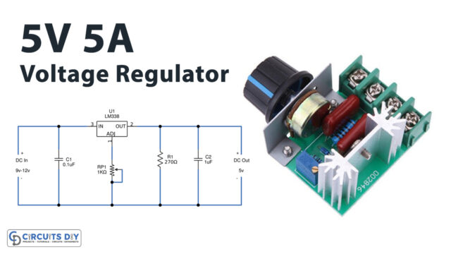
Circuit Diagram
Working Explanation
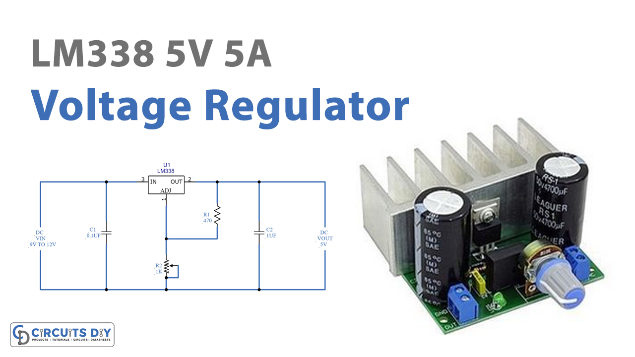
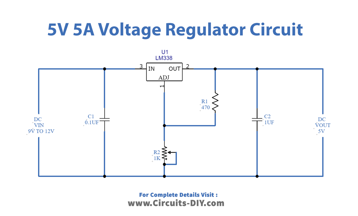
To make this 5 Volt 5 Amp Voltage Regulator we have utilized the LM338 IC, having three terminals. The unregulated supply is provided at pin 3 of an IC. The potentiometer is wired at pin 1. R1 and R2 together make the voltage divider in this circuit. Thus R2 potentiometer together with the resistor R1 decides the output voltage. Changing the potentiometer changes the regulated voltage at the output. 5 Volts, 5 amp voltage can be taken across the output capacitor C2. Both the capacitors are there in the circuit to provide the filtration.
Application and Uses
- The circuit is used for voltage regulation.
- Further, you can use this in current limiting circuits.
- In electronic gadgets.
- Internal combustion engines.