
Introduction
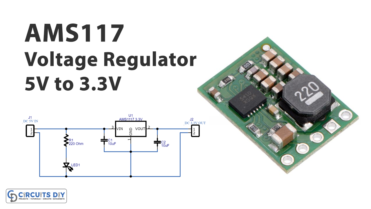
As the name implies, a voltage regulator adjusts or controls the voltages of any electronic circuit. This means, that it takes any input voltage and converts that into a higher or a lower voltage according to the need of the electronic circuit. However, some voltage regulators also include some greater features. For example, they can handle greater voltage spikes, allow reverse polarity protection, and also remove unwanted noise signals. So, today in this article we will make a “Voltage Regulator Circuit 5V to 3.3V”.
To make our circuit, we are using the AMS117 voltage regulator IC. The IC consists of three pins and has a variable voltage range from 1.25V to 13.8V. But, Ic is popularly used to regulate between 3.3V to 5V. Moreover, its output current is 1000mA and the maximum drop-out voltage is 1.3V
Hardware Required
| S.no | Component | Value | Qty |
|---|---|---|---|
| 1. | Voltage Regulator IC | AMS1117 | 1 |
| 2. | LED | – | 1 |
| 3. | Ceramic Capacitor | 10uF | 2 |
| 4. | Resistors | 220 Ohm | 1 |
| 5. | 2 Pin Connector | – | 2 |
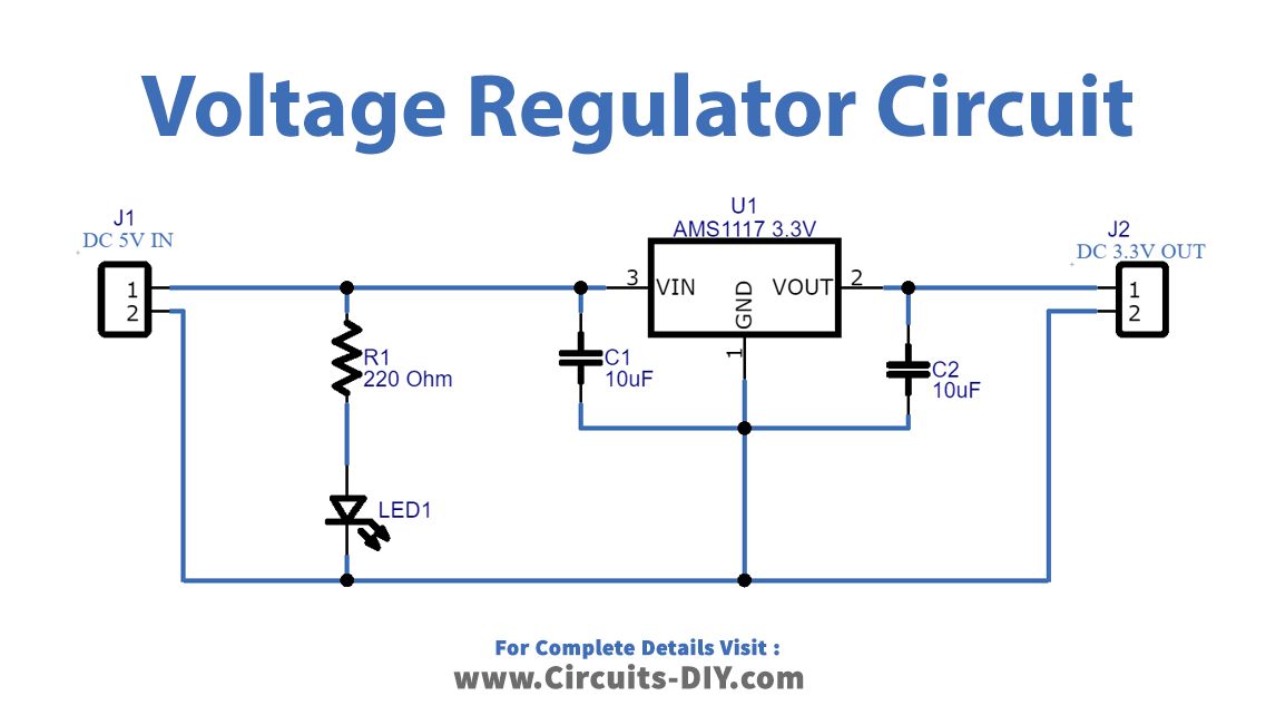
Circuit Diagram
Working Explanation
To make the Voltage Regulator Circuit 5V to 3.3V, we have employed the ASM117 voltage regulator IC having three terminals. V1 where the input is applied. When the input supply is provided, the LED glows to show that there is a supply. Capacitor C1 and C2 are utilized for filtering purposes. The regulated output is taken at pin two and Ic. The circuit is easy to make and simple to understand.
Application and Uses
- It can be used in positive voltage regulation.
- Further, you can use this in current limiting circuits.
- Moreover can be employed in reverse polarity circuits.
- Also, in motor control circuits.
- Mostly utilized in making consumer products.
Related posts:
 LED Dimmer Circuit Using LM317 Voltage Regulator IC
 25V Regulated Power Supply Using LM317T Voltage Regulator
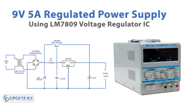 9V/5A Regulated Power Supply Using LM7809 Voltage Regulator
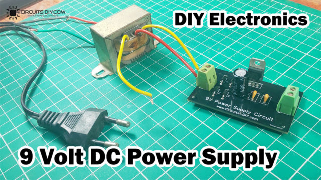 9 Volt Power Supply using LM7809 Voltage Regulator
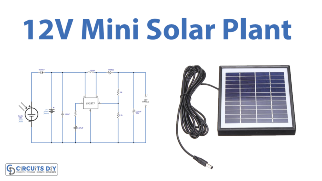 Mini Solar Plant Using LM2577 Voltage Regulator IC
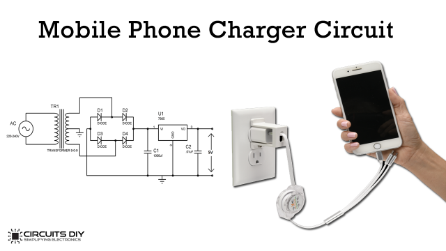 Mobile Phone Charger Circuit - Weekend Project


