Introduction
What if you require an adjustable voltage for the electronic application you’re making but you only have fixed AC voltage available? Now first you need to convert that AC voltage and then also need to make it adjustable. So, we are here to solve your problem. Now, you can make a voltage regulator by yourself.
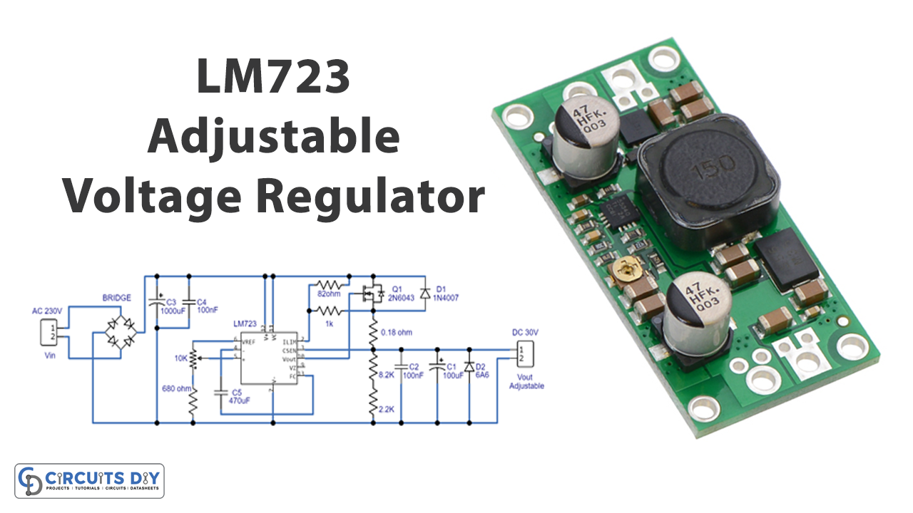
In this tutorial, we are going to Make an “Adjustable Voltage Regulator 30V Circuit”. An adjustable voltage means that output can be adjusted anywhere within the given range. Our circuit is based on the LM723_DIP14 IC which has a wide range of applications in regulators and controllers. Also, this IC draws less current which makes it more promising.
Hardware Components
The following components are required to make an Adjustable Voltage Regulator Circuit
| S.no | Component | Value | Qty |
|---|---|---|---|
| 1. | IC | LM723 | 1 |
| 2. | Transistor | 2N6043 | 1 |
| 3. | Potentiometer | 10K | 1 |
| 4. | Electrolytic Capacitor | 1000µF,470µF,100nF,100nF | 1,1,2,1 |
| 5. | Ceramic Capacitor | 100nF | 1 |
| 6. | Diode Bridge Round | 2W10 | 1 |
| 7. | Resistor | 680Ω, 82k, 1k, 8.2k, 2.2k, 0.18Ω | 1,11,1 |
| 8. | Connector | 2-Pin | 2 |
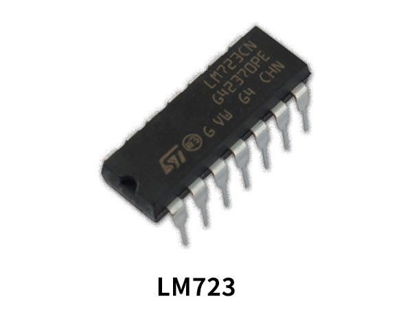
LM723 Pinout
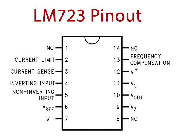
For a detailed description of pinout, dimension features, and specifications download the datasheet of LM723
Adjustable Voltage Regulator Circuit
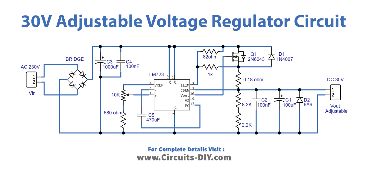
Working Explanation
Our circuit of Adjustable Voltage Regulator includes the full-wave rectifier circuit, designed with the help of four diodes. Thus, this provides the rectified DC voltage which is further get filtered with the help of capacitors c1 and C2. And, then this rectified voltage is given to pins 11 and 12 of the IC. The reference pin is connected to the ground with the help of Potentiometer RV1 and resistor R1. RV1 is there to adjust the output voltage levels at the Vout pin which is connected with the Darlington bipolar power transistor which drives the load.
Application and Uses
- Power supplies.
- Converters.