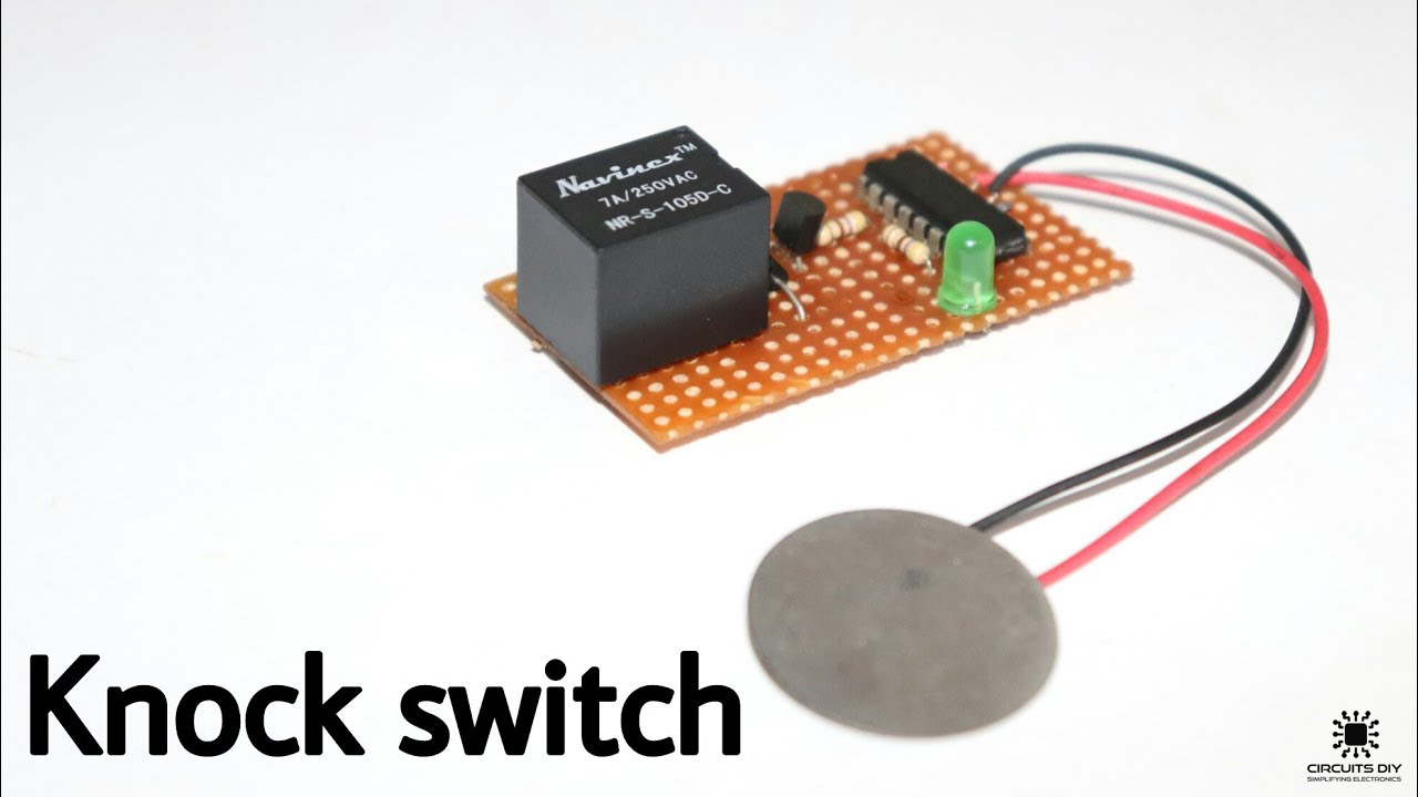
What is a Piezoelectric Knock Switch?
A knock switch is a simple electronic sensor that is used to operate AC/DC appliances with the application of mechanical force. It uses a piezoelectric plate or spring to sense small mechanical vibrations (a knock or a tap) & translates it into a control signal (Vsig) which can be used to control devices such as LEDs, and DC fans, and servos, etc. So, In today’s tutorial, we are going to design a simple Piezoelectric Knock Switch Using CD4017 Counter IC & a 5V SPDT relay.
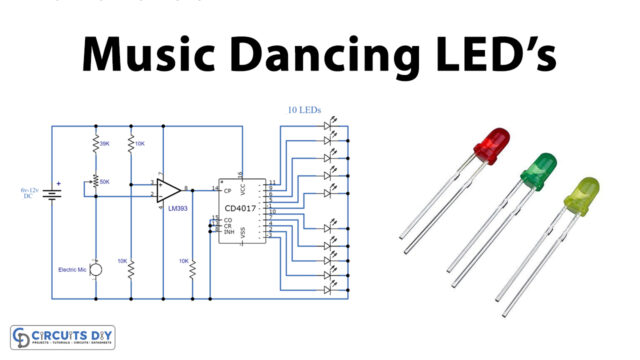
The heart of this Piezoelectric Knock Switch Circuit is a CD4017 counter IC. A CD4017 IC is a 16-pin CMOS decade counter/Divider IC with 10 outputs. It is also known as the ‘Johnson 10 stage decade counter’. It has 10 decoded outputs that give output signals one by one in sequence when a clock signal from the clock input is given.
JLCPCB is the foremost PCB prototype & manufacturing company in china, providing us with the best service we have ever experienced regarding (Quality, Price Service & Time).
Hardware Components
The following components are required to make Piezoelectric Knock Switch Circuit
| S.no | Component | Value | Qty |
|---|---|---|---|
| 1. | Piezo Disc | 20-27mm | 1 |
| 2. | Counter IC | CD4017 | 1 |
| 3. | Relay | SPDT/5V | 1 |
| 4. | Transistor | 2n2222 | 1 |
| 5. | Diode | 1N4007 | 1 |
| 6. | LED | 5mm, 3.5V | 1 |
| 7. | AC Bulb | 220V | 1 |
| 8. | Resistors | 470Ohm | 2 |
| 9. | Soldering Iron | 45W – 65W | 1 |
| 10. | Soldering Wire with Flux | – | 1 |
| 11. | Veroboard | – | 1 |
| 12. | DC Battery | 9V | 1 |
| 13. | Battery clips | – | 1 |
| 14. | AC Wall outlet | 220V | 1 |
| 15. | Jumper Wires | – | As per need |
CD4017 Pinout

For a detailed description of pinout, dimension features, and specifications download the datasheet of CD4017
Useful Steps
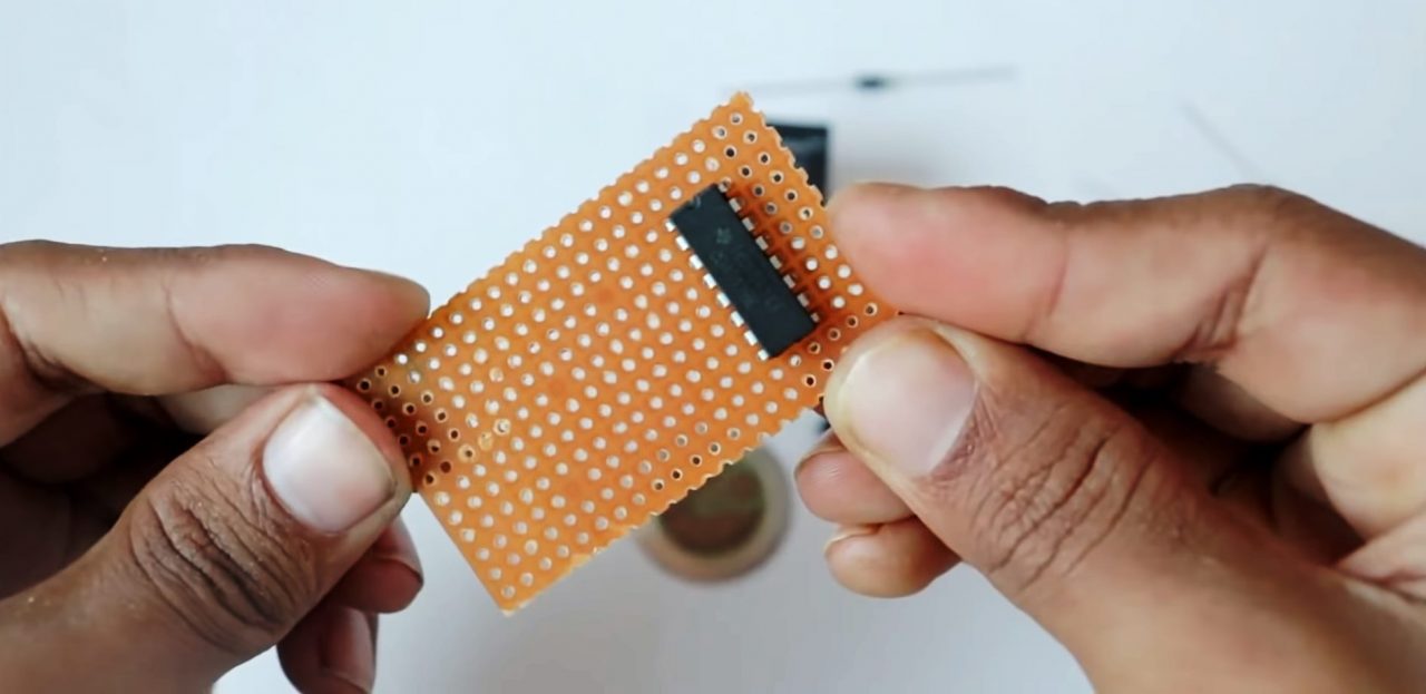
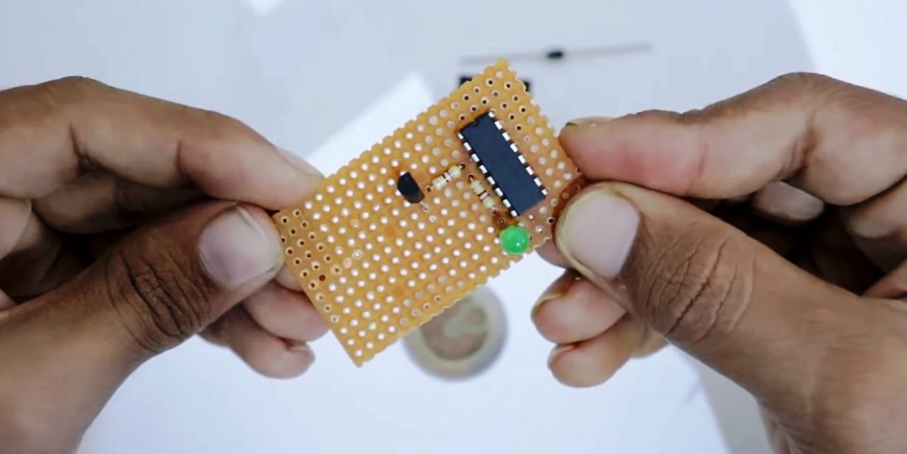
1) Solder the CD4017 IC on the veroboard. After that, solder pins 4 & 15 of the IC with GND of supply.
2) Solder 470 Ohm resistor on Pin 3 of the IC. After that, solder another 470 Ohm resistor between pin 3 of the IC & the +ve terminal of the LED.
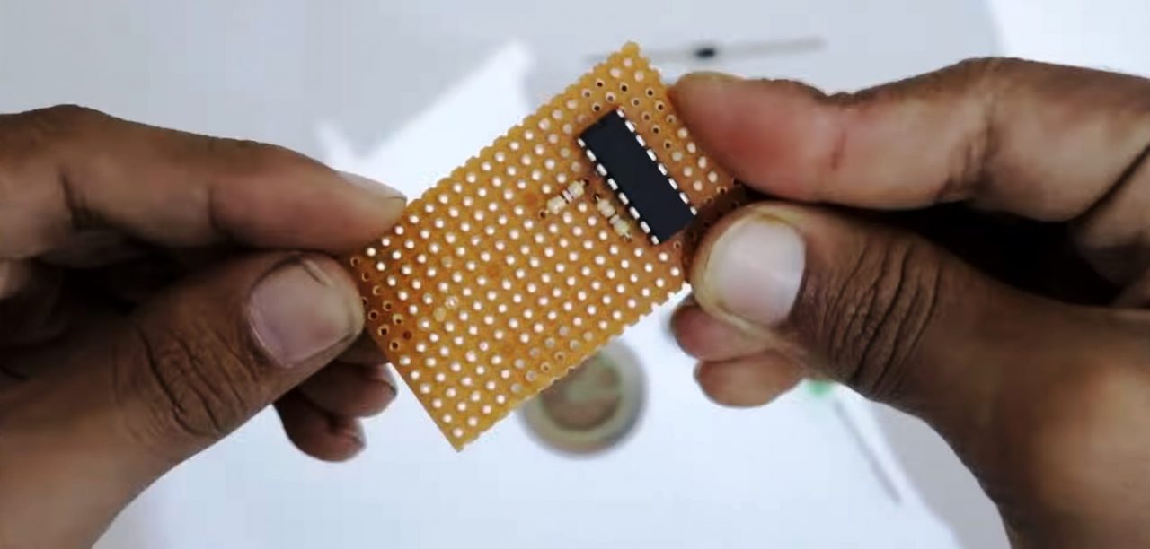
3) Solder the -ve terminal of the LED with pins 13 & 8 of the IC. After that, solder the base of the 2n2222 transistor with the 470 Ohm resistor & emitter with pins 13 & 8 of the IC.
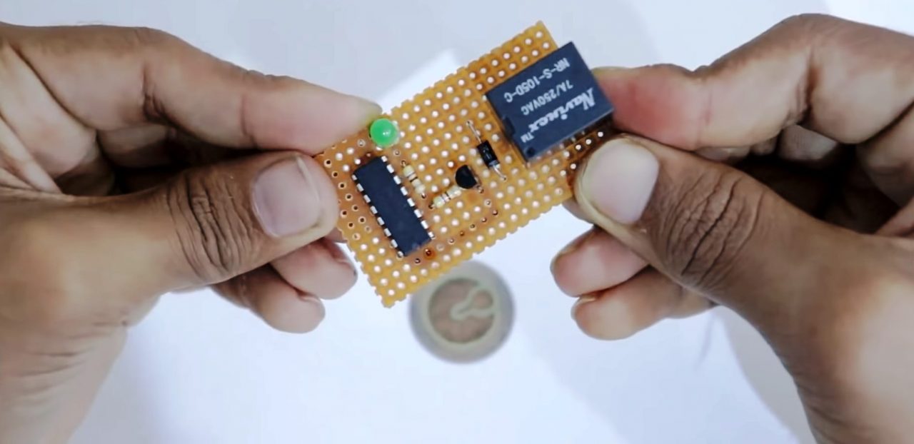
4) Solder the 5V relay on the veroboard & solder a 1N4007 diode on the relay coils.
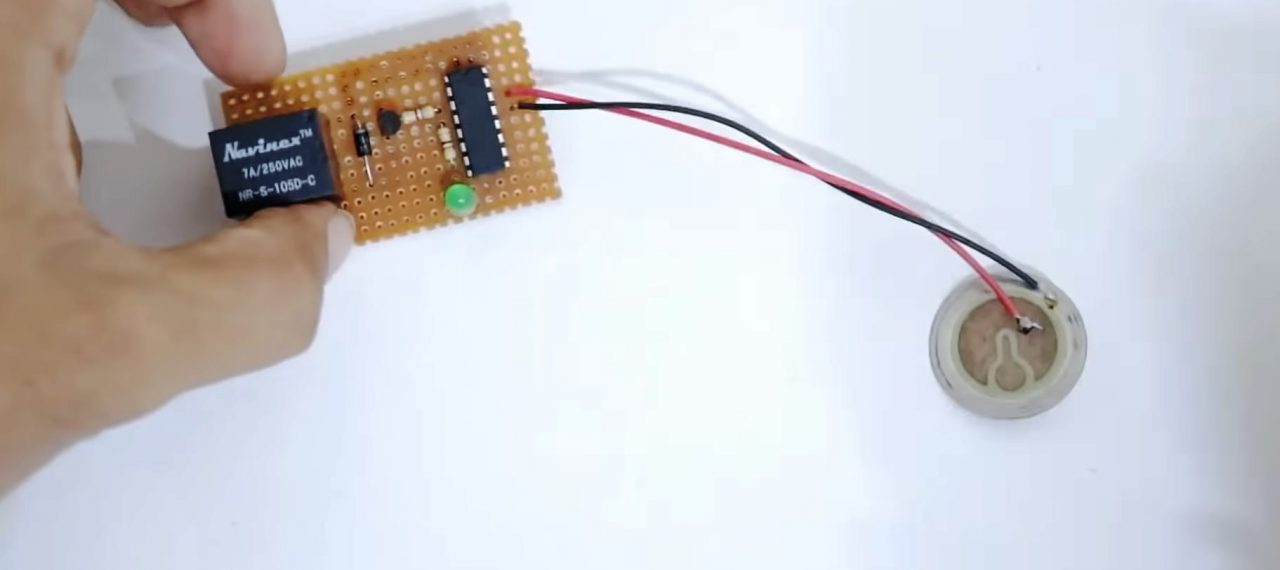
5) Solder the +ve terminal of the piezo disc with pin 14 of the IC & the -ve terminal with pin 13 & 8 of the IC.
6) Solder the +ve terminal of the 9V battery with Pin 16 (Vcc) of the IC & the Cathode terminal of the diode. After that sodler the -ve terminal of the battery with pin 13 & 8 of the IC.
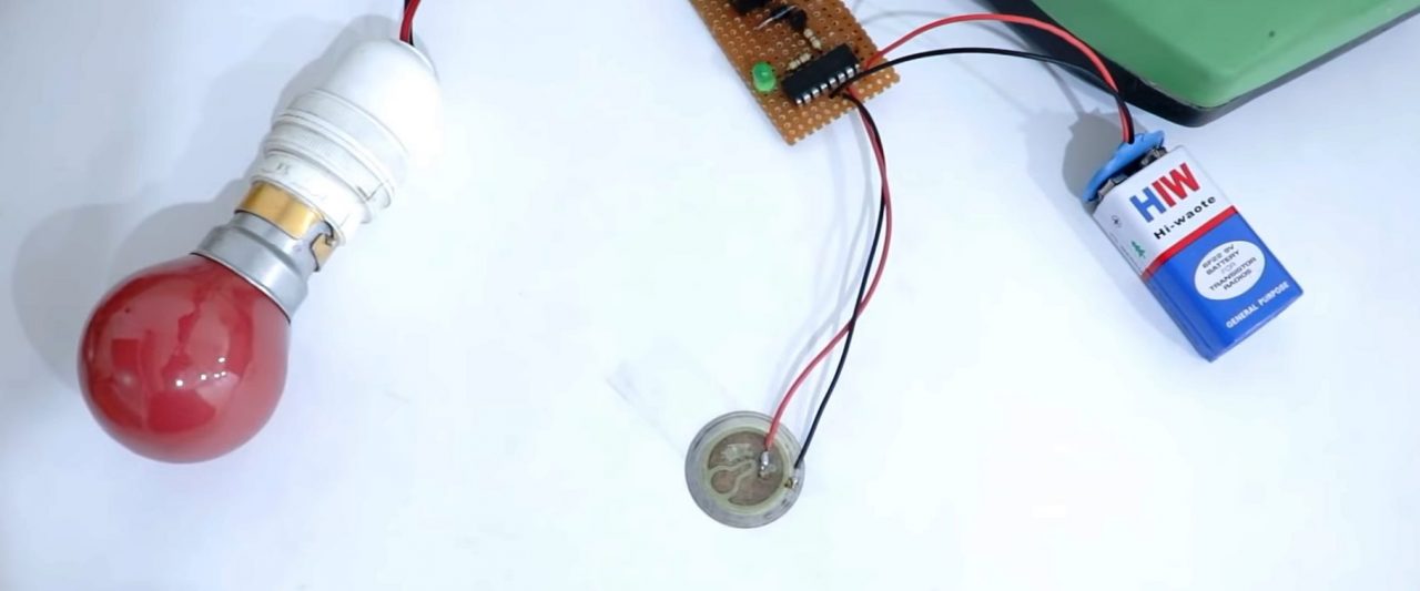
7) Complete the relay circuit by connecting a 220V bulb between the NC & COM terminals of the relay. Now, Power up & test the circuit.
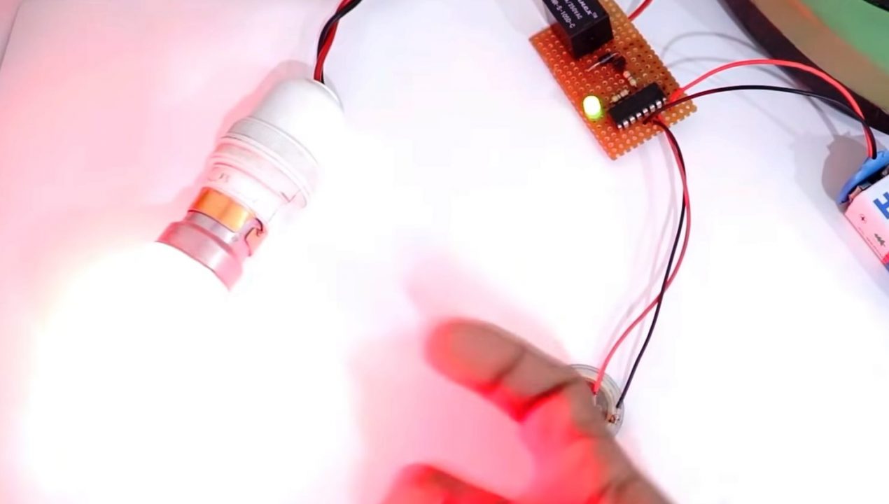
Working Explanation
The working of this circuit is as follows, On tapping/knocking near the piezo disc, a small DC Voltage signal (Vsig) is generated. This Vsig acts as a CLK input to pin 14 of the IC. The Counter IC output (pin 3 ) acts as a control signal to the base of the 2n2222 transistor.
The collector output from the transistor goes on to energize the coils of the 5V SPDT relay. Here we are using a fly-back diode (1N4007) to protect the relay coil from any -ve feedback. When the relay coils are energized, it allows the relay to make any externally connected circuit between its NC & COM terminals. Always make sure that the relay rating is in accordance with the input power supply.
Applications
- Knock switches are used to control household appliances such as light fixtures, fans, motors, etc.