A sound-controlled toggle switch is a circuit that functions according to sound signals such as snapping fingers, a clap, or a whistle. This circuit is quite sensitive and can detect low sound signals easily. The output of the switch remains either low or high until the mic senses the next sound signal since it’s a sensitive circuit it can function as a control circuit for AC loads through an SPDT relay. The sensitivity of this circuit can be controlled with a 100K variable resistor.
The sound-controlled toggle switch is very useful for our daily life needs, for example, it can respond to a knock on the door or can provide burglar protection if someone tries to open the door or break something the lights will turn on indicating the presence of burglars.
Hardware Components
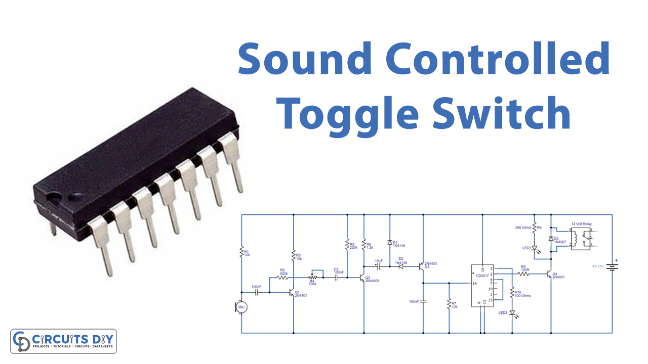
Sound Controlled Toggle Switch Circuit
| S.no | Components | Value | Qty |
|---|---|---|---|
| 1. | Decade Counter IC | CD4017 | 1 |
| 2. | LED | – | 2 |
| 3. | SPDT Relay | 9v/12V | 1 |
| 4. | Electret Microphone | – | 1 |
| 5. | Ceramic Capacitor | 100nF | 3 |
| 6. | Transistor | 2N4401, 2N4403 | 3, 1 |
| 7. | Diode | 1N4148, 1N4007 | 1, 1 |
| 8. | Resistor | 10K, 620K, 220K, 1.2K, 390 ohms, 120R, 100 ohms | 3, 1, 1, 1, 1, 1, 1 |
| 9. | Battery | 9-12V | 1 |
| 10. | Breadboard | – | 1 |
| 11. | Electrolytic Capacitor | 10µF | 1 |
| 12. | Battery Clips | – | 1 |
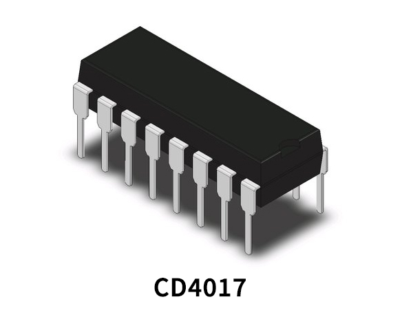
CD4017 Pinout
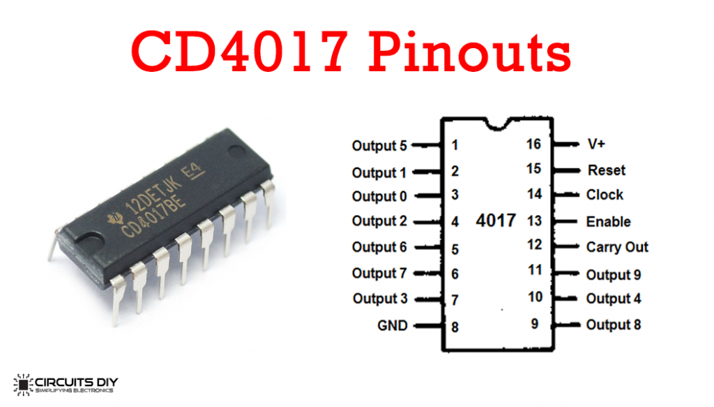
For a detailed description of pinout, dimension features, and specifications download the datasheet of CD4017
2N4401 Pinout
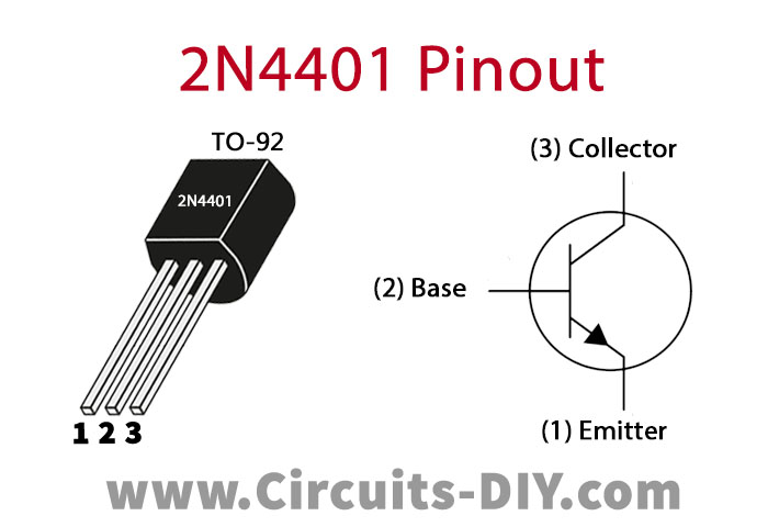
For a detailed description of pinout, dimension features, and specifications download the datasheet of 2N4401
2N4403 Pinout
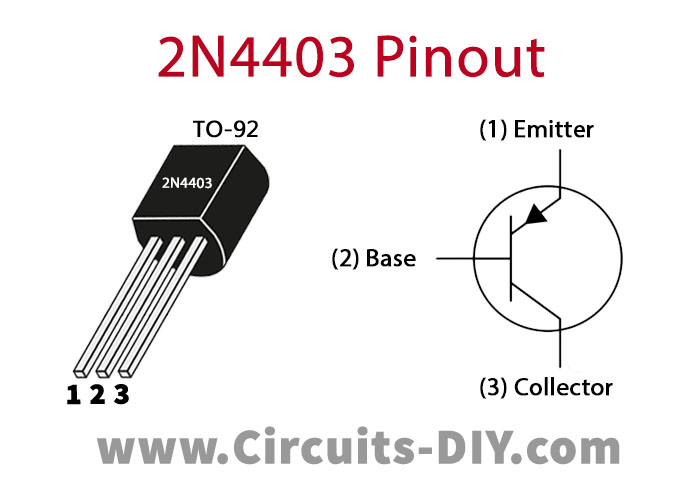
For a detailed description of pinout, dimension features, and specifications download the datasheet of 2N4403
Sound Controlled Toggle Switch Circuit

Working Explanation
The operating voltage of this circuit is 9 to 12V DC. The objective of the two transistors Q1 and Q2 is to amplify the audio signals coming from the electret microphone. The diodes rectify audio signals received from filter capacitor C3, turning the transistor Q3 switch ON. After the Q3 turns ON it provides positive pulses at the clock input pin of the IC (pin 14).
The IC CD4017 is wired as a toggle switch so when it receives positive pulses on the input pin its output is high and low at pins 2 and 3. When the microphone receives the first sound signal the relay and LED1 will activate till another sound signal is received which will deactivate the relay and LED1. The Q4 transistor drives the relay.
Applications and Uses
- Home Automation
- Burglar Protection
- Turning on and off electrical appliances
- Sound-triggered recording systems
- Sound-triggered lamps