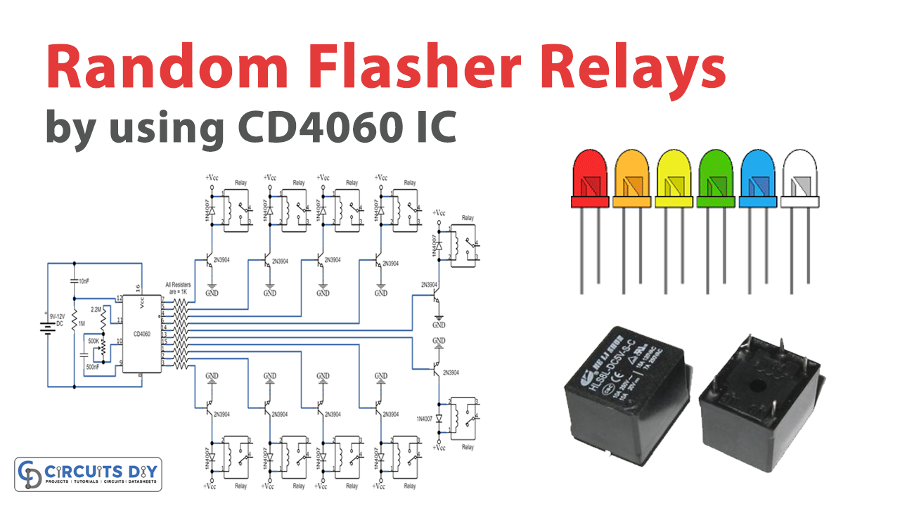
In this tutorial, we are demonstrating a project of a “Random Flasher Relay” using the CD4060 IC. There are numerous circuits and packs available that can Flash or switch the number of relays periodically, arbitrarily, or sequentially.
This random relay flasher circuit consistently ON and OFF the ten relay switches arbitrarily. The circuit can be utilized for an assortment of flashing or switching applications for home decoration, shops, cars, and so on. You can utilize it to make an astonishing Flashing light framework by utilizing ideal AC or DC bulbs, LEDs, LED strips, and so on.
Right now, we are utilizing a CD4060 flip-flop oscillator IC with the combination of ten 2N3904 transistors and relays.
Hardware Components
The following components are required to make a Random Flasher Relay Circuit
| S.no | Components | Value | Qty |
| 1. | IC | CD4060 | 1 |
| 2. | Variable resistor | 500K | 1 |
| 3. | Ceramic Capacitor | 10nF, 500nF | 1 |
| 4. | Capacitor | – | 1 |
| 5. | Resistor | 1MΩ, 2.2MΩ, 1kΩ | 1, 1, 10 |
| 8. | Relays | 12V | 10 |
| 9. | Transistors | 2N3904 | 10 |
| 10. | DC supply or Battery | 9V – 12V | 1 |
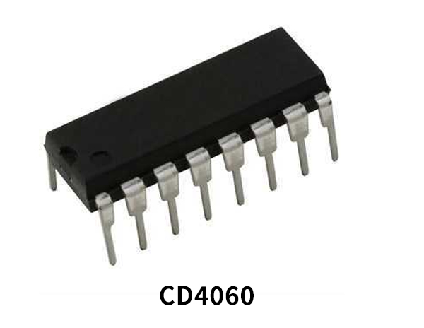
CD4060 Pinout

For a detailed description of pinout, dimension features, and specifications download the datasheet of CD4060
2N3904 Pinout
For a detailed description of pinout, dimension features, and specifications download the datasheet of 2N3904
Random Flasher Relay Circuit

Working Explanation
To comprehend the circuit, first, you have to see how a relay functions. A relay is an electromagnetic switch that typically works by a generally low electric current that can turn ON or OFF a lot larger electric current. The core of a relay is an electromagnet, a coil of wire that turns into a temporary magnet when it gets electric power. We utilize ten 2N3904 transistors to give adequate current to the relays.
The circuit works around a 4060 CMOS IC. The ON or OFF speed of the relay can be controlled with the 500K variable resistors. The ON-OFF speed can likewise be balanced by expanding or diminishing the estimation value of the 500nF capacitor. All the focus stamps towards +Vcc ought to be associated with the positive rail of the supply and all the ground focuses ought to be associated with the negative of the supply. The working voltage of the circuit is 9V to 12V DC. All the relays ought to be 12 volts. The circuit can likewise work on lower voltages like 5V or 6V DC. In the event that you need to utilize the circuit on 5V or 6V, at that point utilize 6V relays.
Applications and Uses
- The use of transistor with relays help to switch or control high-power devices such as motors, electromagnets, and others
- On a large scale, it might be used in flasher and relay units in vehicles to control the flash rate of vehicle directional indicators.
- To regularize the power switching in electronic devices.