Contents
hide
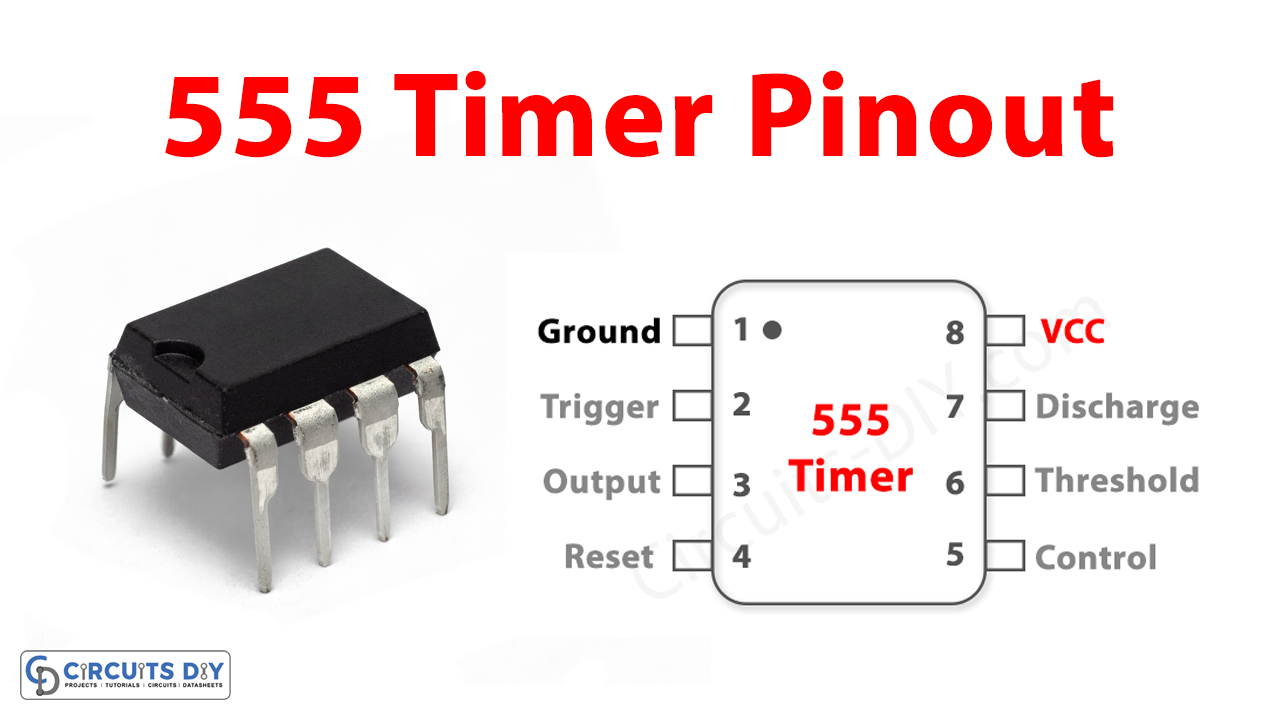
The 555 Timer IC, often hailed as the “workhorse” of the electronics world, is a versatile integrated circuit that has found its way into countless electronic projects. Understanding its pinout is essential for harnessing its capabilities
Pinout
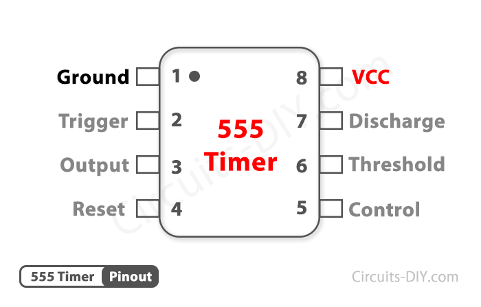
Pin Configuration
| Pin No | Pin Name | Description |
|---|---|---|
| 1 | Ground | Ground Reference Voltage 0V |
| 2 | Trigger | This pin is normally connected to the load as it is the only pin with output driven waveform |
| 3 | Output | A negative pulse applied to this pin to disable or reset the timer. When not used for reset 4 I purposes, it should be connected to VCC to avoid false triggering |
| 4 | Reset | Compares the voltage applied to the terminal with a reference voltage of 2/3 Vcc. The 6 I amplitude of the voltage applied to this terminal is responsible for the set state of the flip-flop |
| 5 | Control | Controls the threshold and trigger levels. It determines the pulse width of the output 5 Voltage I waveform. An external voltage applied to this pin can also be used to modulate the output waveform |
| 6 | Threshold | Open collector output which discharges a capacitor between intervals (in phase with output). 7 I It toggles the output from high to low when the voltage reaches 2/3 of the supply voltage |
| 7 | Discharge | Open collector output which discharges a capacitor between intervals (in phase with output). 7 I It toggles the output from high to low when the voltage reaches 2/3 of the supply voltage |
| 8 | VCC | Supply Voltage (Typical = 5V, Maximum = 18V) |


