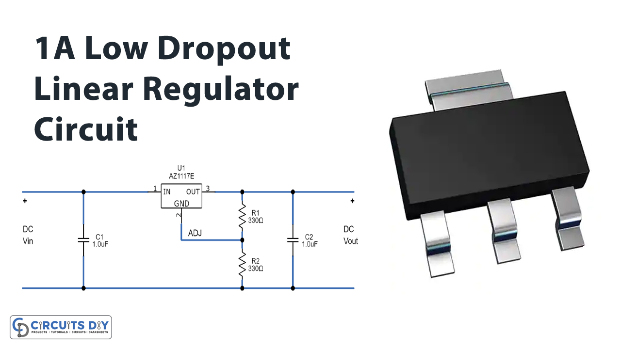
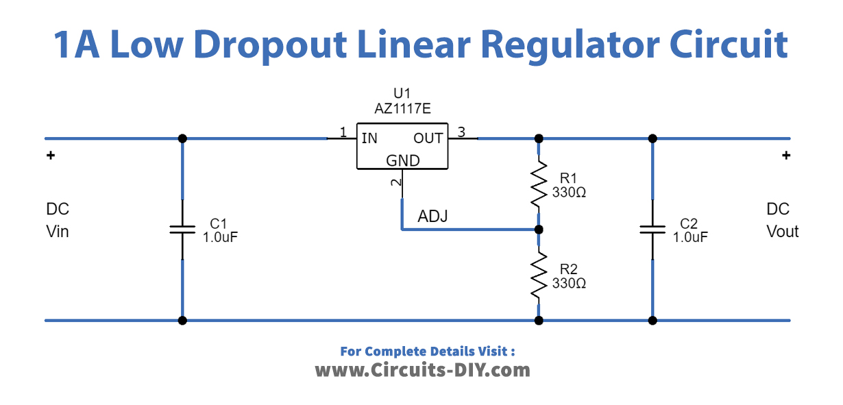
In this tutorial, we are going to make a “1 A Low Dropout Linear Regulator circuit”.
As previously it is quite difficult to design regulator circuits with low dropout regulation and high output current. A linear regulator is a system used to maintain a steady voltage. The resistance of the regulator varies by both the input voltage and the load, resulting in constant voltage output. Diodes Incorporated provided us with a ready-made solution by AZ1117E. We have designed a 1.0A low dropout linear regulator circuit by using AZ1117E. The AZ1117E series is a three-terminal low dropout positive voltage regulator, with a typical dropout of 1.1V at 1A of load current, decreasing at lower load currents.
The AZ1117E has been optimized for low voltage where transient response and minimum input voltage are critical. The device features an on-chip thermal shutdown. It also includes a bandgap reference and a current limiting circuit. This IC has an on-chip thermal protection setup to avoid high current ambient temperature. The AZ1117E is available in an adjustable version and six fixed output versions of 1.2, 1.5,1.8, 2.5, 3.3, and 5V. The adjustable version can set the output voltage with two external resistors. The AZ1117E series is available in the industry-standard package SOT223. It will provide good load regulation at 1A current output. It can take up to 16 volts as input and Gives 1.5 Volt to 12 Volt as output.
Hardware Components
The following components are required to make Linear Regulator Circuit
| S.no | Component | Value | Qty |
|---|---|---|---|
| 1. | IC | AZ1117E | 1 |
| 2. | Capacitor | 1µF | 2 |
| 3. | Resistor | 330Ω | 2 |
| 4. | Connecting Wires | – | 1 |
| 5. | Power Supply | 5V | 1 |
AZ1117E Pinout
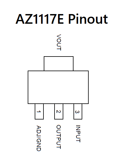
For a detailed description of pinout, dimension features, and specifications download the datasheet of AZ1117E
Linear Regulator Circuit
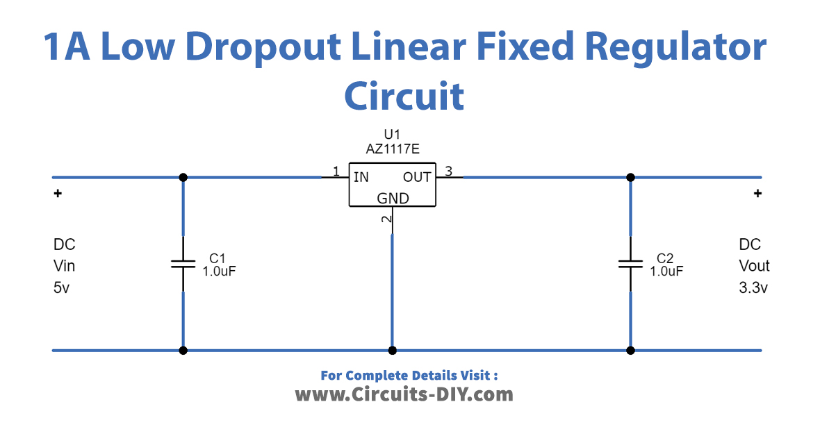
Fixed Regulator Circuit
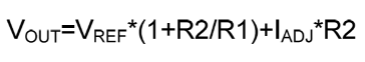
Output Voltage Calculation
Working Explanation
As we can see in the circuit, the main part of the circuit is AZ1117E. It has three terminals named pin1 ADJ/GND, pin2 OUTPUT, and pin3 INPUT. First for an adjustable voltage regulator we need to put a voltage divider setup at the output using two resistors with AZ1117E. So, we have used R1 and R2 resistors and connected the ADJ pin between the voltage divider resisters. The output voltage depends on the value of these two resistors (R1 and R2). Now we used Capacitors C1 and C2, which work as voltage filters.
For fixed voltage regulator design, we will require only filter capacitors at input and output. We have used two 1.0µF ceramic capacitors. And then we need to choose the fixed output voltage range IC (1.2V, 1.5V, 1.8V, 2.5V, 3.3V, and 5.0V) as per our requirement.
Applications
- Used in TVs and LCD Monitors
- PC Peripherals: Notebooks, Motherboards
- STB